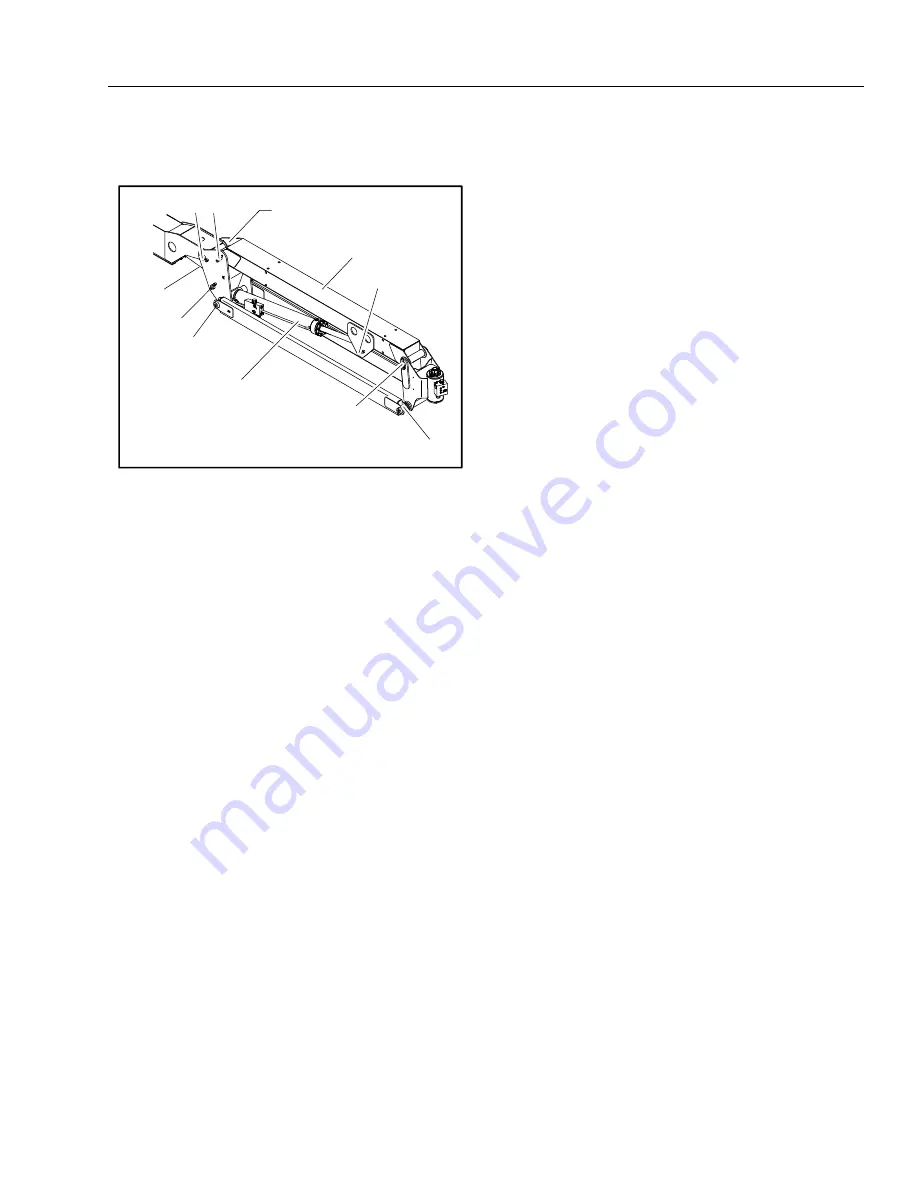
SECTION 4 - BOOM & PLATFORM
31215031
4-23
3.
Remove mounting hardware from lift cylinder pin #7.
Using a suitable brass drift and hammer, remove the cyl-
inder pin from articulating jib boom.
Inspection
NOTE:
When inspecting pins and bearings Refer to Section 2.5 -
Pins and Composite Bearing Repair Guidelines.
1.
Inspect fly boom pivot pin for wear, scoring, tapering
and ovality, or other damage. Replace pins as necessary.
2.
Inspect fly boom pivot attach points for scoring, taper-
ing and ovality, or other damage. Replace pins as neces-
sary.
3.
Inspect inner diameter of fly boom pivot bearings for
scoring, distortion, wear, or other damage. Replace bear-
ings as necessary.
4.
Inspect lift cylinder attach pin for wear, scoring, tapering
and ovality, or other damage. Ensure pin surfaces are
protected prior to installation. Replace pins as neces-
sary.
5.
Inspect inner diameter of rotator attach point bearings
for scoring, distortion, wear, or other damage.
6.
Inspect all threaded components for damage such as
stretching, thread deformation, or twisting. Replace as
necessary.
7.
Inspect structural units of jib boom assembly for bend-
ing, cracking, separation of welds, or other damage.
Replace boom sections as necessary.
Assembly
1.
Align lift cylinder with attach holes in jib assembly.
Using a soft head mallet, install cylinder pin #7 into jib
and secure with mounting hardware.
2.
Align rotator support with attach hole in jib assembly.
Using a soft head mallet, install rotator support pin #6
into jib and secure with mounting hardware.
3.
Align bottom tubes with attach holes in rotator support.
Using a soft head mallet, install rotator support pin #5
into jib assembly and secure with mounting hardware.
4.
Align jib assembly with attach hole in jib boom pivot
weldment. Using a soft head mallet, install rotator sup-
port pin #4 into jib assembly and secure with mounting
hardware.
5.
Align bottom tubes with attach holes in jib boom pivot
weldment. Using a soft head mallet, install rotator sup-
port pin #3 into jib boom pivot weldment and secure
with mounting hardware.
Installation
1.
Align jib boom pivot weldment with attach holes in fly
boom assembly. Using a soft head mallet, install pivot
pin #2 into fly boom assembly and secure with mount-
ing hardware.
2.
Align the slave leveling cylinder with attach holes in jib
boom pivot weldment. Using a soft head mallet, install
slave leveling cylinder pin #1 into articulating jib boom
pivot weldment and secure with mounting hardware.
6
5
SLAVE
CYLINDER
7
JIB LIFT
CYLINDER
JIB PIVOT
1
2 4
JIB
3
Figure 4-11. Jib Assembly
Go
to
Discount-Equipment.com
to
order
your
parts


