SECTION 3 - CHASSIS & TURNTABLE
3-18
31215031
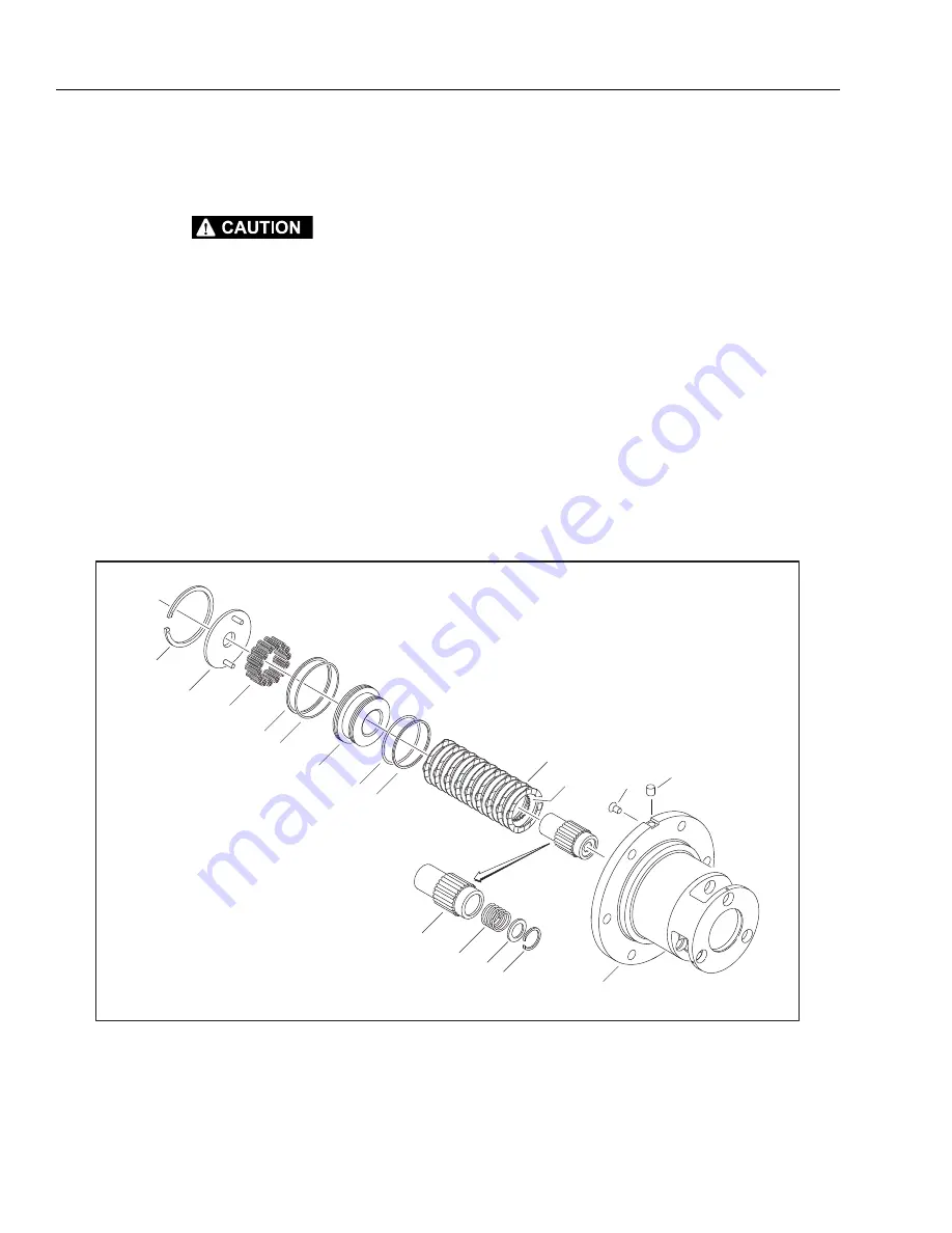
Spindle-Brake Disassembly
NOTE:
Units with integral Input Brake (8) only.
COMPRESSED SPRINGS CAN FLY OUT AND CAUSE SEVERE EYE DAMAGE OR
OTHER INJURIES. WEAR EYE PROTECTION WHEN PERFORMING THESE PROCE-
DURES.
1.
Install two 1/4"-20 x 5/8" Flat Head Capscrews (22)
through Pressure Plate (8B) into Piston (8A). Tighten
incrementally until spring force is taken off Retaining
Ring (8C).
NOTE:
Flat Head Capscrews (22) are for transit and service only
and are removed before shipping new units. They are
included in most brake repair kits.
2.
Using retaining ring pliers, remove Retaining Ring (8C)
from groove in Spindle (1A).
3.
Back Flat Head Capscrews (22) incrementally out of Piston
(8A) until spring force is relieved from Pressure Plate (8B).
Remove Flat Head Capscrews (22) and Pressure Plate (8B)
from brake cavity in Spindle (1A).
4.
Remove Compression Springs (8L) from Piston (8A).
5.
Using an air hose, slowly and carefully pressurize brake
port in Spindle (1A) until Piston (8A) comes out of piston
bore of Spindle (1A). Pull Piston (8A) out of Spindle (1A)
by hand.
6.
Remove Backup Rings (8E and 8H) and O-rings (8D and
8F) from grooves in Piston (8A).
7.
Remove Rotors (8J) and Stators (8K) from brake cavity in
Spindle (1A).
8.
Remove Coupling Subassembly (7) from brake cavity in
Spindle (1A).
9.
Remove Retaining Ring (1K) from internal groove using
appropriate tool.
10.
Remove Spacer (1M) and Spring (1L) from bore of Cou-
pling (7).
11.
Remove Plastic Plug (12) and Pipe Plug (21) from Spindle
(1A) if applicable.
Figure 3-17. Spindle Brake Disassembly
Go
to
Discount-Equipment.com
to
order
your
parts


