SECTION 3 - CHASSIS & TURNTABLE
3-52
3121160
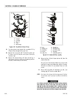
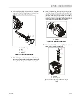
8.
Carefully place the turntable on a suitably supported
trestle.
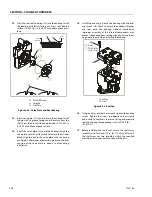
9.
Use a suitable tool to scribe a line on the outer race of
the swing bearing and the frame. This line will aid in
aligning the bearing upon installation. Remove the bolts
and washers which attach the outer race of the bearing
to the frame. Discard the bolts. Use suitable lifting
equipment to remove the bearing from the frame, then
move the bearing to a clean, suitably supported work
area.
INSTALLATION
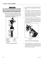
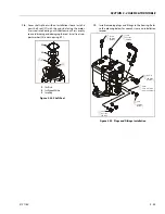
1.
Using suitable lifting equipment, carefully lower the
swing bearing into position on the frame. Ensure the
scribed line of the outer race of the bearing aligns with
the scribed line on the frame. If a new swing bearing is
used, ensure that the filler plug fitting is at 90 degrees
from the fore and aft center line of the frame.
JLG INDUSTRIES RECOMMENDS THAT ALL REMOVED BEARING BOLTS BE DIS-
CARDED AND REPLACED WITH NEW BOLTS. SINCE THE SWING BEARING IS THE
ONLY STRUCTURAL LINK BETWEEN THE FRAME AND TURNTABLE, IT IS IMPER-
ATIVE THAT SUCH REPLACEMENT HARDWARE MEETS JLG SPECIFICATIONS.
USE OF GENUINE JLG HARDWARE IS HIGHLY RECOMMENDED.
2.
Apply a light coating of JLG Threadlocker P/N 0100019
to the new bearing bolts, and loosely install the bolts
and washers through the frame and outer race of bear-
ing.
IF COMPRESSED AIR OR ELECTRICALLY OPERATED IMPACT WRENCH IS USED
FOR TIGHTENING THE BEARING ATTACHMENT BOLTS, THE TORQUE SETTING
ACCURACY OF THE TOOL SHOULD BE CHECKED PRIOR TO USE.
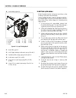
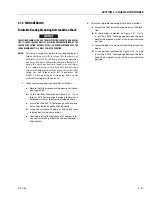
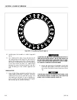
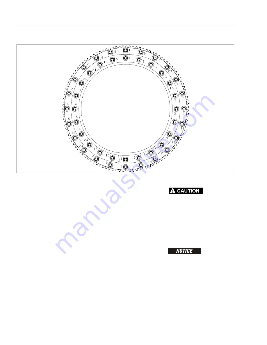
Figure 3-42. Swing Bearing Torque Sequence.
Summary of Contents for 740AJ
Page 2: ......
Page 55: ...SECTION 3 CHASSIS TURNTABLE 3121160 3 3 This page left blank intentionally...
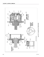
Page 116: ...SECTION 3 CHASSIS TURNTABLE 3 64 3121160 Figure 3 44 Swing Hub Prior to SN 0300074383...
Page 203: ...SECTION 3 CHASSIS TURNTABLE 3121160 3 151 Figure 3 77 EFI Component Location...
Page 206: ...SECTION 3 CHASSIS TURNTABLE 3 154 3121160 Figure 3 78 ECM EPM Identification ECM EPM...
Page 224: ...SECTION 3 CHASSIS TURNTABLE 3 172 3121160 Figure 3 83 Deutz EMR 2 Troubleshooting Flow Chart...
Page 228: ...SECTION 3 CHASSIS TURNTABLE 3 176 3121160 Figure 3 87 EMR 2 Engine Plug Pin Identification...
Page 229: ...SECTION 3 CHASSIS TURNTABLE 3121160 3 177 Figure 3 88 EMR 2 Vehicle Plug Pin Identification...
Page 230: ...SECTION 3 CHASSIS TURNTABLE 3 178 3121160 Figure 3 89 EMR2 Fault Codes Sheet 1 of 5...
Page 231: ...SECTION 3 CHASSIS TURNTABLE 3121160 3 179 Figure 3 90 EMR2 Fault Codes Sheet 2 of 5...
Page 232: ...SECTION 3 CHASSIS TURNTABLE 3 180 3121160 Figure 3 91 EMR2 Fault Codes Sheet 3 of 5...
Page 233: ...SECTION 3 CHASSIS TURNTABLE 3121160 3 181 Figure 3 92 EMR2 Fault Codes Sheet 4 of 5...
Page 234: ...SECTION 3 CHASSIS TURNTABLE 3 182 3121160 Figure 3 93 EMR2 Fault Codes Sheet 5 of 5...
Page 303: ...SECTION 4 BOOM PLATFORM 3121160 4 31 Figure 4 20 Rotator Assembly HELAC...
Page 460: ...SECTION 5 BASIC HYDRAULIC INFORMATION AND SCHEMATICS 5 116 3121160 NOTES...
Page 467: ...SECTION 6 JLG CONTROL SYSTEM 3121160 6 7 Figure 6 2 ADE Block Diagram...
Page 534: ...SECTION 6 JLG CONTROL SYSTEM 6 74 3121160 NOTES...
Page 580: ...SECTION 7 BASIC ELECTRICAL INFORMATION SCHEMATICS 7 46 3121160 NOTES...
Page 581: ......

