SECTION 3 - CHASSIS & TURNTABLE
3-142
3121160
Engine Module and Sensors
CRANKSHAFT POSITION (CKP) SENSOR
The crankshaft position (CKP) sensor provides a signal used by
the Engine Module to calculate the ignition sequence. The CKP
sensor initiates the reference pulses which the Engine Module
uses to calculate RPM and crankshaft position.
CAMSHAFT POSITION (CMP) SENSOR AND SIGNAL
The camshaft position (CMP) sensor sends a CMP signal to the
Engine Module. The Engine Module uses this signal as a "sync
pulse" to trigger the injectors in the proper sequence. The
Engine Module uses the CMP signal to indicate the position of
the #1 piston during its power stroke. The CMP uses a Hall
Effect sensor to measure piston position. This allows the
Engine Module to calculate true sequential fuel injection (SFI)
mode of operation. If the Engine Module detects an incorrect
CMP signal while the engine is running, DTC 53 will set. If the
CMP signal is lost while the engine is running, the fuel injec-
tion system will shift to a calculated sequential fuel injection
mode based on the last fuel injection pulse, and the engine
will continue to nun. As long as the fault is present, the engine
can be restarted. It will run in the previously established injec-
tion sequence.
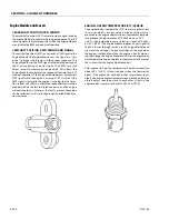
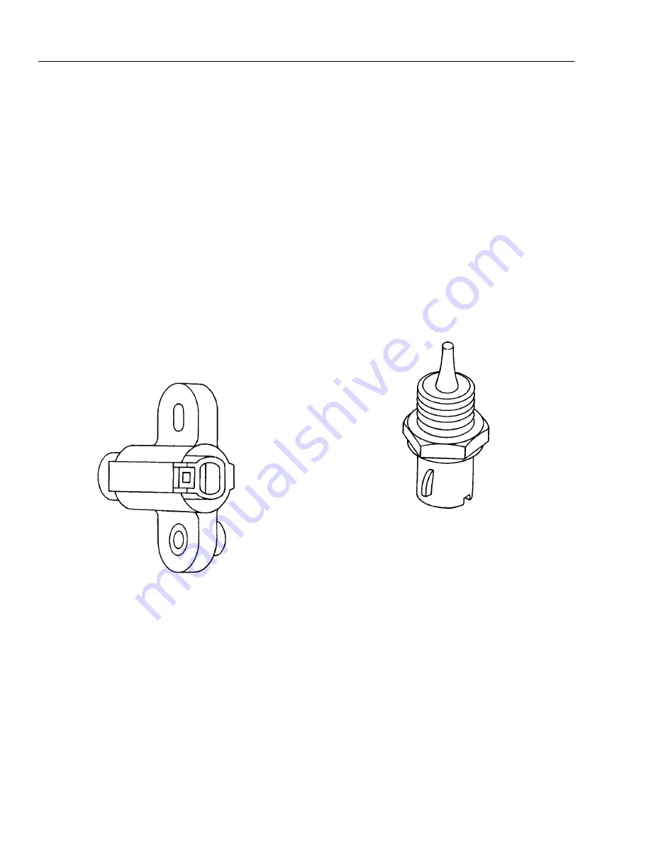
ENGINE COOLANT TEMPERATURE (ECT) SENSOR
The engine coolant temperature (ECT) sensor is a g thermistor
(a resistor which changes value based on temperature)
mounted in the engine coolant stream. Low coolant tempera-
ture produces a high resistance of 100,000 ohms at -40°C
(-40°F). High temperature causes a low resistance of 70 ohms
at 130°C (266°F). The Engine Module supplies a 5-volt signal to
the ECT sensor through resistors in the Engine Module and
measures the voltage. The signal voltage will be high when
the engine is cold and low when the engine is hot. By measur-
ing the voltage, the Engine Module calculates the engine cool-
ant temperature. Engine coolant temperature affects most of
the systems that the Engine Module controls.
After engine start-up, the temperature should rise steadily to
about 85°C (185°F). it then stabilizes when the thermostat
opens. If the engine has not been run for several hours (over-
night), the engine coolant temperature and intake air temper-
ature displays should be close to each other. A fault in the
engine coolant sensor circuit will set DTC 33 or DTC 43.
Summary of Contents for 740AJ
Page 2: ......
Page 55: ...SECTION 3 CHASSIS TURNTABLE 3121160 3 3 This page left blank intentionally...
Page 116: ...SECTION 3 CHASSIS TURNTABLE 3 64 3121160 Figure 3 44 Swing Hub Prior to SN 0300074383...
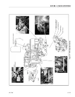
Page 203: ...SECTION 3 CHASSIS TURNTABLE 3121160 3 151 Figure 3 77 EFI Component Location...
Page 206: ...SECTION 3 CHASSIS TURNTABLE 3 154 3121160 Figure 3 78 ECM EPM Identification ECM EPM...
Page 224: ...SECTION 3 CHASSIS TURNTABLE 3 172 3121160 Figure 3 83 Deutz EMR 2 Troubleshooting Flow Chart...
Page 228: ...SECTION 3 CHASSIS TURNTABLE 3 176 3121160 Figure 3 87 EMR 2 Engine Plug Pin Identification...
Page 229: ...SECTION 3 CHASSIS TURNTABLE 3121160 3 177 Figure 3 88 EMR 2 Vehicle Plug Pin Identification...
Page 230: ...SECTION 3 CHASSIS TURNTABLE 3 178 3121160 Figure 3 89 EMR2 Fault Codes Sheet 1 of 5...
Page 231: ...SECTION 3 CHASSIS TURNTABLE 3121160 3 179 Figure 3 90 EMR2 Fault Codes Sheet 2 of 5...
Page 232: ...SECTION 3 CHASSIS TURNTABLE 3 180 3121160 Figure 3 91 EMR2 Fault Codes Sheet 3 of 5...
Page 233: ...SECTION 3 CHASSIS TURNTABLE 3121160 3 181 Figure 3 92 EMR2 Fault Codes Sheet 4 of 5...
Page 234: ...SECTION 3 CHASSIS TURNTABLE 3 182 3121160 Figure 3 93 EMR2 Fault Codes Sheet 5 of 5...
Page 303: ...SECTION 4 BOOM PLATFORM 3121160 4 31 Figure 4 20 Rotator Assembly HELAC...
Page 460: ...SECTION 5 BASIC HYDRAULIC INFORMATION AND SCHEMATICS 5 116 3121160 NOTES...
Page 467: ...SECTION 6 JLG CONTROL SYSTEM 3121160 6 7 Figure 6 2 ADE Block Diagram...
Page 534: ...SECTION 6 JLG CONTROL SYSTEM 6 74 3121160 NOTES...
Page 580: ...SECTION 7 BASIC ELECTRICAL INFORMATION SCHEMATICS 7 46 3121160 NOTES...
Page 581: ......

