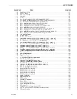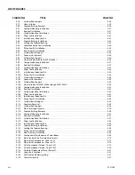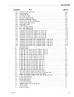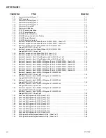
SECTION 1 - SPECIFICATIONS
3121160
1-3
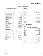
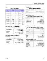
Tires
Drive System (Prior to SN 0300138447)
Drive System (SN 0300138447 through
0300185827)
Swing System
Hydraulic Drive Pump
Variable Displacement Pump
Hydraulic Load Sense Pump
Table 1-9. Tire Specifications
Size
Type
Ply
Rating
Load
Range
Pressure
IN 385/65D 19.5
pneumatic
16
H
95 psi
(6.5 bar)
IN 445/55D 19.5
pneumatic
16
H
85 psi
(6.0 bar)
15 X 19.5
pneumatic
16
H
95 psi
(6.5 bar)
18 X 19.5
pneumatic
16
H
95 psi
(6.5 bar)
IN 385/65D 19.5
foam-filled
16
H
N/A
IN 445/55D 19.5
foam-filled
16
H
N/A
15 X 19.5
foam-filled
16
H
95 psi
(6.5 bar)
18 X 19.5
foam-filled
16
H
95 psi
(6.5 bar)
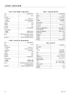
Table 1-10. Drive System Specifications
Drive Motor Displacement
2.75 cu. in. max. 1.1 cu. in. min.
(45 cm
3
max.12 cm
3
min.)
Drive Hub Ratio.
59.3:1
Drive Brake
Automatic spring applied, hydraulically
released disc brakes.
Table 1-11. Drive System Specifications
Drive Motor Displacement
2.13 cu. in. max. 0.63 cu. in. min.
(35 cc max. 10.3 cc min.)
Drive Hub Ratio
87:1
Drive Brake
Automatic spring applied, hydraulically
released disc brakes.
Table 1-12. Swing System Specifications
Swing Motor Displacement
4 cu. in. (66 cm
3
)
Swing Brake
Automatic spring applied hydraulically
released disc brakes
Swing Hub Ratio
36.13:1
Table 1-14. Variable Displacement Pump Specifications
Type
Variable, Displacement Open Loop Pump
Low Pressure Relief Valve Setting
400 psi (27.5 bar)
High Pressure Relief Valve Setting
2600 psi (179 bar)
Pump Circuit
Open
Displacement Vgmax
2.74 in
3
(45 cm
3
)
Pressure and Flow Control
DFR1
Rotation
Clockwise
NBR seals
Nitrile rubber to DIN ISO 1629
Shaft
SAE 1.00 in. (2.54 cm) splined
Table 1-15. Hydraulic Load Sense Pump Specifications
Pump Displacement
2.1cu. in. (34.4 cm
3
) Max.
Pump Output
15.5 GPM (59 lpm) @ 1800 RPM
Stand By Pressure
400 psi.(27.5 bar) @ 1800 RPM
High Pressure Relief
High Pressure Relief - 2700 psi.(186 bar)
Rotation
Clockwise
Table 1-13. Hydraulic Drive Pump Specifications
Pump Output
35.5 GPM (134 lpm) @ 2800 RPM
Pump Displacement
2.8 cu. in. (46 cm
3
)
Charge Pump Displacement
0.85 cu. in. (14 cm
3
)
Charge Pump Output
9.5 GPM (37 ipm) @ 2800 RPM
Charge Pump Pressure
400 PSI. (27.5 Bar)@ 2800 RPM
Clockwise Rotation
Summary of Contents for 740AJ
Page 2: ......
Page 55: ...SECTION 3 CHASSIS TURNTABLE 3121160 3 3 This page left blank intentionally...
Page 116: ...SECTION 3 CHASSIS TURNTABLE 3 64 3121160 Figure 3 44 Swing Hub Prior to SN 0300074383...
Page 203: ...SECTION 3 CHASSIS TURNTABLE 3121160 3 151 Figure 3 77 EFI Component Location...
Page 206: ...SECTION 3 CHASSIS TURNTABLE 3 154 3121160 Figure 3 78 ECM EPM Identification ECM EPM...
Page 224: ...SECTION 3 CHASSIS TURNTABLE 3 172 3121160 Figure 3 83 Deutz EMR 2 Troubleshooting Flow Chart...
Page 228: ...SECTION 3 CHASSIS TURNTABLE 3 176 3121160 Figure 3 87 EMR 2 Engine Plug Pin Identification...
Page 229: ...SECTION 3 CHASSIS TURNTABLE 3121160 3 177 Figure 3 88 EMR 2 Vehicle Plug Pin Identification...
Page 230: ...SECTION 3 CHASSIS TURNTABLE 3 178 3121160 Figure 3 89 EMR2 Fault Codes Sheet 1 of 5...
Page 231: ...SECTION 3 CHASSIS TURNTABLE 3121160 3 179 Figure 3 90 EMR2 Fault Codes Sheet 2 of 5...
Page 232: ...SECTION 3 CHASSIS TURNTABLE 3 180 3121160 Figure 3 91 EMR2 Fault Codes Sheet 3 of 5...
Page 233: ...SECTION 3 CHASSIS TURNTABLE 3121160 3 181 Figure 3 92 EMR2 Fault Codes Sheet 4 of 5...
Page 234: ...SECTION 3 CHASSIS TURNTABLE 3 182 3121160 Figure 3 93 EMR2 Fault Codes Sheet 5 of 5...
Page 303: ...SECTION 4 BOOM PLATFORM 3121160 4 31 Figure 4 20 Rotator Assembly HELAC...
Page 460: ...SECTION 5 BASIC HYDRAULIC INFORMATION AND SCHEMATICS 5 116 3121160 NOTES...
Page 467: ...SECTION 6 JLG CONTROL SYSTEM 3121160 6 7 Figure 6 2 ADE Block Diagram...
Page 534: ...SECTION 6 JLG CONTROL SYSTEM 6 74 3121160 NOTES...
Page 580: ...SECTION 7 BASIC ELECTRICAL INFORMATION SCHEMATICS 7 46 3121160 NOTES...
Page 581: ......

