SECTION 3 - CHASSIS & TURNTABLE
3121160
3-217
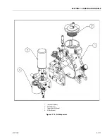
Intake Control
The intake control consists of two main sub-assemblies:
1.
Inlet Valve Assembly:
The inlet valve opening/closing
(load/unload) is controlled by admitting/exhausting
pilot air pressure through the solenoid valve to the pis-
ton which is part of the inlet valve assembly. The inlet
valve is not a routine maintenance item. Maintenance
kits are available which include replacement seals, etc.
2.
Solenoid Valve:
Attaches directly to the inlet valve and
responds to signals from the pressure switch to admit/
vent pilot air pressure to the inlet valve to control load/
unload. In the unlikely event of failure this item is to be
replaced as a complete item.
Minimum Pressure Valve
Normally factory set to 65 psig (4.5 Bar). Provides two main
functions:
1.
Maintains Minimum Pressure:
Prevents downstream
air to pass until compressor system is up to minimum
pressure valve setting which aids in maintaining good
oil supply to the compressor and also is a requirement
for good oil separation.
2.
Back Pressure Check Valve:
Allows for compressor to
be unloaded to lower pressure than supply air line sys-
tem and permits compressor air pressure to be totally
relieved when stopped.
This valve is not a routine maintenance item. Seals and
replacement parts are available.
Compressor Thermal Valve
Controls compressor oil temperature and permits for rapid
compressor oil warm up. Commences to pass oil through
cooler at 160°F (71°C) and is fully open at 185°F (85°C).
Safety Shutdown Systems
Protection for over-pressure and/or over-temperature is pro-
vided. If either condition should occur the diverter valve
should activate to divert hydraulic fluid back to tank and the
compressor will stop, the reset on instrument panel will pop
out and stay out until reset. Reason for shutdown should be
investigated before pressing reset.
Periodically (every 6 months or every 500 hours) the shutdown
system should be tested as follows: Compressor operating,
close service valve and allow compressor to unload (2 minutes
or more) then touch across button on gauge face to Bezel sur-
rounding the respective gauge with coin or screwdriver. Reset
button should pop out and compressor stop. Switch off com-
pressor and press reset button to reactive shutdown system.
Troubleshooting
The information contained in the Troubleshooting Chart has
been compiled from information gathered. It contains symp-
toms and usual causes for the most common types or prob-
lem. All available data concerning the trouble should be
systematically analyzed before undertaking any repairs or
component replacement.
A visual inspection is worth performing for almost all prob-
lems and may avoid unnecessary additional damage to the
machine. The procedures which can be performed in the least
amount of time and with the least amount of removal or disas-
sembly of parts should be performed first.
BEFORE WORKING ON ANY MACHINE, ENSURE IT IS SHUT DOWN AND ISO-
LATED, AIR PRESSURE RELIEVED, AND UNIT HAS COOLED DOWN.
Summary of Contents for 740AJ
Page 2: ......
Page 55: ...SECTION 3 CHASSIS TURNTABLE 3121160 3 3 This page left blank intentionally...
Page 116: ...SECTION 3 CHASSIS TURNTABLE 3 64 3121160 Figure 3 44 Swing Hub Prior to SN 0300074383...
Page 203: ...SECTION 3 CHASSIS TURNTABLE 3121160 3 151 Figure 3 77 EFI Component Location...
Page 206: ...SECTION 3 CHASSIS TURNTABLE 3 154 3121160 Figure 3 78 ECM EPM Identification ECM EPM...
Page 224: ...SECTION 3 CHASSIS TURNTABLE 3 172 3121160 Figure 3 83 Deutz EMR 2 Troubleshooting Flow Chart...
Page 228: ...SECTION 3 CHASSIS TURNTABLE 3 176 3121160 Figure 3 87 EMR 2 Engine Plug Pin Identification...
Page 229: ...SECTION 3 CHASSIS TURNTABLE 3121160 3 177 Figure 3 88 EMR 2 Vehicle Plug Pin Identification...
Page 230: ...SECTION 3 CHASSIS TURNTABLE 3 178 3121160 Figure 3 89 EMR2 Fault Codes Sheet 1 of 5...
Page 231: ...SECTION 3 CHASSIS TURNTABLE 3121160 3 179 Figure 3 90 EMR2 Fault Codes Sheet 2 of 5...
Page 232: ...SECTION 3 CHASSIS TURNTABLE 3 180 3121160 Figure 3 91 EMR2 Fault Codes Sheet 3 of 5...
Page 233: ...SECTION 3 CHASSIS TURNTABLE 3121160 3 181 Figure 3 92 EMR2 Fault Codes Sheet 4 of 5...
Page 234: ...SECTION 3 CHASSIS TURNTABLE 3 182 3121160 Figure 3 93 EMR2 Fault Codes Sheet 5 of 5...
Page 303: ...SECTION 4 BOOM PLATFORM 3121160 4 31 Figure 4 20 Rotator Assembly HELAC...
Page 460: ...SECTION 5 BASIC HYDRAULIC INFORMATION AND SCHEMATICS 5 116 3121160 NOTES...
Page 467: ...SECTION 6 JLG CONTROL SYSTEM 3121160 6 7 Figure 6 2 ADE Block Diagram...
Page 534: ...SECTION 6 JLG CONTROL SYSTEM 6 74 3121160 NOTES...
Page 580: ...SECTION 7 BASIC ELECTRICAL INFORMATION SCHEMATICS 7 46 3121160 NOTES...
Page 581: ......

