SECTION
4
- BOO
M
& PLATFOR
M
4-4
3121160
4.2
ROTATOR AND SLAVE CYLINDER
Removal
1.
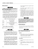
Tag and disconnect hydraulic lines to rotator and slave
cylinder. Use suitable container to retain any residual
hydraulic fluid. Cap hydraulic lines and ports.
2.
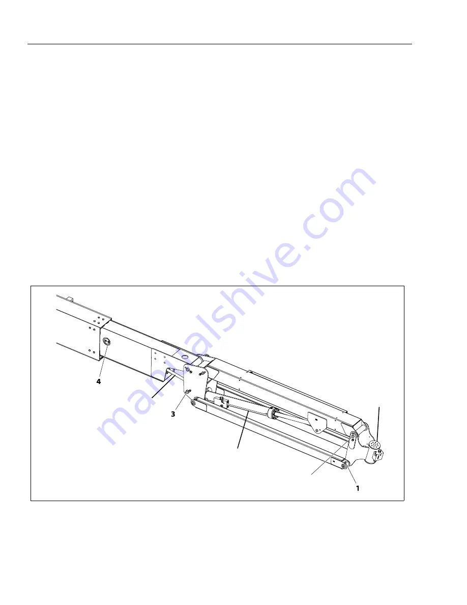
Supporting the rotator, remove hardware from pin #1.
Using a suitable brass drift and hammer remove pin #1
from the jib assembly.
3.
Remove the hardware from pin #2. Using a suitable
brass drift and hammer, remove pin #2 from the jib
assembly and remove the rotator.
4.
Telescope the fly section out approximately 20 in.
(50.8 cm) to gain access to the slave leveling cylinder.
5.
Supporting the slave cylinder, remove the hardware
from pin #3. Using a suitable brass drift and hammer
remove pin #3 from the jib assembly.
6.
Remove the hardware from pin #4. Using a suitable
brass drift and hammer remove pin #4 from the fly
boom. Remove the slave cylinder.
Installation
1.
Telescope the fly section out approximately 20 in.
(50.8 cm) to gain access to the slave leveling cylinder.
2.
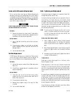
Support the slave cylinder. Using a suitable brass drift
and hammer, install pin #4 to the fly boom. Install hard-
ware securing pin #4.
3.
Using brass drift and hammer install pin #3 to jib assem-
bly and install the slave cylinder. Install hardware secur-
ing pin #3.
4.
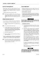
Support the rotator. using a suitable brass drift and
hammer, install pin #2 to the jib assembly. Install hard-
ware securing pin #2.
5.
Using brass drift and hammer install pin #1 to jib assem-
bly and install the rotator. Install hardware securing pin
#1.
6.
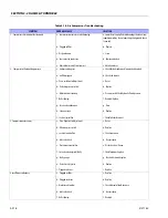
Remove tag and reconnect the hydraulic lines to the
rotator and the slave cylinder.
2
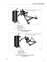
Figure 4-4. Location of Components - Rotator and Slave Cylinder
SLAVE CYLINDER
ROTATOR
JIB LIFT CYLINDER
Summary of Contents for 740AJ
Page 2: ......
Page 55: ...SECTION 3 CHASSIS TURNTABLE 3121160 3 3 This page left blank intentionally...
Page 116: ...SECTION 3 CHASSIS TURNTABLE 3 64 3121160 Figure 3 44 Swing Hub Prior to SN 0300074383...
Page 203: ...SECTION 3 CHASSIS TURNTABLE 3121160 3 151 Figure 3 77 EFI Component Location...
Page 206: ...SECTION 3 CHASSIS TURNTABLE 3 154 3121160 Figure 3 78 ECM EPM Identification ECM EPM...
Page 224: ...SECTION 3 CHASSIS TURNTABLE 3 172 3121160 Figure 3 83 Deutz EMR 2 Troubleshooting Flow Chart...
Page 228: ...SECTION 3 CHASSIS TURNTABLE 3 176 3121160 Figure 3 87 EMR 2 Engine Plug Pin Identification...
Page 229: ...SECTION 3 CHASSIS TURNTABLE 3121160 3 177 Figure 3 88 EMR 2 Vehicle Plug Pin Identification...
Page 230: ...SECTION 3 CHASSIS TURNTABLE 3 178 3121160 Figure 3 89 EMR2 Fault Codes Sheet 1 of 5...
Page 231: ...SECTION 3 CHASSIS TURNTABLE 3121160 3 179 Figure 3 90 EMR2 Fault Codes Sheet 2 of 5...
Page 232: ...SECTION 3 CHASSIS TURNTABLE 3 180 3121160 Figure 3 91 EMR2 Fault Codes Sheet 3 of 5...
Page 233: ...SECTION 3 CHASSIS TURNTABLE 3121160 3 181 Figure 3 92 EMR2 Fault Codes Sheet 4 of 5...
Page 234: ...SECTION 3 CHASSIS TURNTABLE 3 182 3121160 Figure 3 93 EMR2 Fault Codes Sheet 5 of 5...
Page 303: ...SECTION 4 BOOM PLATFORM 3121160 4 31 Figure 4 20 Rotator Assembly HELAC...
Page 460: ...SECTION 5 BASIC HYDRAULIC INFORMATION AND SCHEMATICS 5 116 3121160 NOTES...
Page 467: ...SECTION 6 JLG CONTROL SYSTEM 3121160 6 7 Figure 6 2 ADE Block Diagram...
Page 534: ...SECTION 6 JLG CONTROL SYSTEM 6 74 3121160 NOTES...
Page 580: ...SECTION 7 BASIC ELECTRICAL INFORMATION SCHEMATICS 7 46 3121160 NOTES...
Page 581: ......

