SECTION 1 - SPECIFICATIONS
3121160
1-11
1.9
DRAINING OIL BUILD UP FROM THE PROPANE
REGULATOR (PRIOR TO SN 0300134626)
During the course of normal operation oils may build
inside the primar y and secondar y chambers of the
propane pressure regulator. These oils may be a result of
poor fuel quality, contamination of the fuel supply chain, or
regional variation in the make up of the fuel. If the build up
of the oil is significant this can effect the operation of the
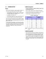
fuel control system. Refer to “Maintenance and Lubrica-
tion” on page 7. for maintenance intervals. More frequent
draining may be required if the fuel supply has been con-
taminated.
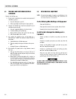
FOR BEST RESULTS WARM THE ENGINE TO OPERATING TEMPERATURE BEFORE
DRAINING. THIS WILL ALLOW THE OILS TO BE LIQUID AND FLOW FREELY
FROM THE REGULATOR.
1.
Move the equipment to a well ventilated area. Ensure
there are no external ignition sources.
2.
Start the engine and bring to operating temperature.
3.
With the engine running, close the manual tank valve
and run the engine out of fuel.
4.
Push in the Emergency Switch once the engine stops.
5.
Disconnect the electrical connection to the LPG fuel
temperature sensor in the auxiliary fuel port of the EPR.
6.
Remove the retainer clip for the LPG fuel temperature
sensor and remove the sensor from the regulator body.
NOTE:
Have a small container ready to collect oil that will drain
freely from the regulator at this point.
7.
Once all of the oil has been drained, reinstall the LPG
fuel temperature sensor and reconnect the electrical
connector.
8.
Open the fuel tank manual valve.
9.
Start the engine and verify all connections are secure.
10.
Dispose of any drained oil in a safe and proper fashion.
Summary of Contents for 740AJ
Page 2: ......
Page 55: ...SECTION 3 CHASSIS TURNTABLE 3121160 3 3 This page left blank intentionally...
Page 116: ...SECTION 3 CHASSIS TURNTABLE 3 64 3121160 Figure 3 44 Swing Hub Prior to SN 0300074383...
Page 203: ...SECTION 3 CHASSIS TURNTABLE 3121160 3 151 Figure 3 77 EFI Component Location...
Page 206: ...SECTION 3 CHASSIS TURNTABLE 3 154 3121160 Figure 3 78 ECM EPM Identification ECM EPM...
Page 224: ...SECTION 3 CHASSIS TURNTABLE 3 172 3121160 Figure 3 83 Deutz EMR 2 Troubleshooting Flow Chart...
Page 228: ...SECTION 3 CHASSIS TURNTABLE 3 176 3121160 Figure 3 87 EMR 2 Engine Plug Pin Identification...
Page 229: ...SECTION 3 CHASSIS TURNTABLE 3121160 3 177 Figure 3 88 EMR 2 Vehicle Plug Pin Identification...
Page 230: ...SECTION 3 CHASSIS TURNTABLE 3 178 3121160 Figure 3 89 EMR2 Fault Codes Sheet 1 of 5...
Page 231: ...SECTION 3 CHASSIS TURNTABLE 3121160 3 179 Figure 3 90 EMR2 Fault Codes Sheet 2 of 5...
Page 232: ...SECTION 3 CHASSIS TURNTABLE 3 180 3121160 Figure 3 91 EMR2 Fault Codes Sheet 3 of 5...
Page 233: ...SECTION 3 CHASSIS TURNTABLE 3121160 3 181 Figure 3 92 EMR2 Fault Codes Sheet 4 of 5...
Page 234: ...SECTION 3 CHASSIS TURNTABLE 3 182 3121160 Figure 3 93 EMR2 Fault Codes Sheet 5 of 5...
Page 303: ...SECTION 4 BOOM PLATFORM 3121160 4 31 Figure 4 20 Rotator Assembly HELAC...
Page 460: ...SECTION 5 BASIC HYDRAULIC INFORMATION AND SCHEMATICS 5 116 3121160 NOTES...
Page 467: ...SECTION 6 JLG CONTROL SYSTEM 3121160 6 7 Figure 6 2 ADE Block Diagram...
Page 534: ...SECTION 6 JLG CONTROL SYSTEM 6 74 3121160 NOTES...
Page 580: ...SECTION 7 BASIC ELECTRICAL INFORMATION SCHEMATICS 7 46 3121160 NOTES...
Page 581: ......

