SECTION 5 - BASIC HYDRAULIC INFOR
M
ATION AND SCHE
M
ATICS
5-20
3121160
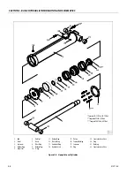
Main Boom Lift Cylinder
DISASSEMBLY
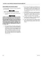
DISASSEMBLY OF THE CYLINDER SHOULD BE PERFORMED ON A CLEAN WORK
SURFACE IN A DIRT FREE WORK AREA.
1.
Connect a suitable auxiliary hydraulic power source to
the cylinder port block fitting.
DO NOT FULLY EXTEND CYLINDER TO THE END OF STROKE. RETRACT CYLINDER
SLIGHTLY TO AVOID TRAPPING PRESSURE.
2.
Operate the hydraulic power source and extend the cyl-
inder. Shut down and disconnect the power source.
Adequately support the cylinder rod, if applicable.
3.
Remove the counterbalance holding valves and fittings
from the cylinder port block. Discard o-rings.
4.
Place the cylinder barrel into a suitable holding fixture.
5.
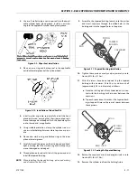
Mark cylinder head and barrel with a center punch for
easy realignment. Using an allen wrench, loosen the cyl-
inder head retainer capscrews and remove capscrews
from cylinder barrel.
6.
Attach a suitable pulling device to the cylinder rod port
block end or cylinder rod end, as applicable.
EXTREME CARE SHOULD BE TAKEN WHEN REMOVING THE C YLINDER ROD,
HEAD, AND PISTON. AVOID PULLING THE ROD OFF-CENTER, WHICH COULD
CAUSE DAMAGE TO THE PISTON AND CYLINDER BARREL SURFACES.
7.
With the barrel clamped securely, apply pressure to the
rod pulling device and carefully withdraw the complete
rod assembly from the cylinder barrel.
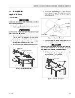
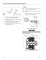
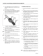
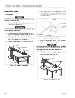
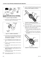
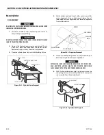
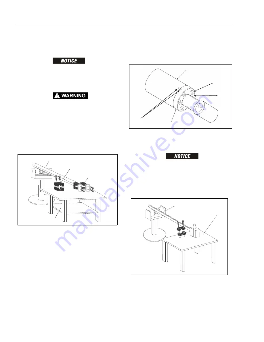
ROD SUPPORT
PROTECTED ROD CLAMP
BARREL CLAMP
SUPPORT TABLE
Figure 5-32. Cylinder Barrel Support
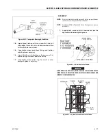
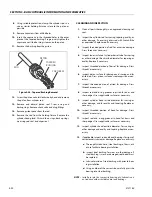
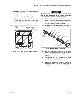
CAPSCREW
BARREL
PUNCH MARK
CYLINDER HEAD
WASHER
RING
Figure 5-33. Capscrew Removal
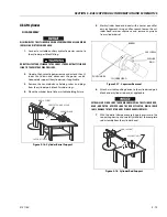
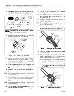
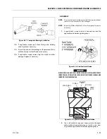
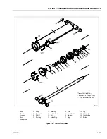
SUPPORT TABLE
ROD SUPPORT
Figure 5-34. Cylinder Rod Support
Summary of Contents for 740AJ
Page 2: ......
Page 55: ...SECTION 3 CHASSIS TURNTABLE 3121160 3 3 This page left blank intentionally...
Page 116: ...SECTION 3 CHASSIS TURNTABLE 3 64 3121160 Figure 3 44 Swing Hub Prior to SN 0300074383...
Page 203: ...SECTION 3 CHASSIS TURNTABLE 3121160 3 151 Figure 3 77 EFI Component Location...
Page 206: ...SECTION 3 CHASSIS TURNTABLE 3 154 3121160 Figure 3 78 ECM EPM Identification ECM EPM...
Page 224: ...SECTION 3 CHASSIS TURNTABLE 3 172 3121160 Figure 3 83 Deutz EMR 2 Troubleshooting Flow Chart...
Page 228: ...SECTION 3 CHASSIS TURNTABLE 3 176 3121160 Figure 3 87 EMR 2 Engine Plug Pin Identification...
Page 229: ...SECTION 3 CHASSIS TURNTABLE 3121160 3 177 Figure 3 88 EMR 2 Vehicle Plug Pin Identification...
Page 230: ...SECTION 3 CHASSIS TURNTABLE 3 178 3121160 Figure 3 89 EMR2 Fault Codes Sheet 1 of 5...
Page 231: ...SECTION 3 CHASSIS TURNTABLE 3121160 3 179 Figure 3 90 EMR2 Fault Codes Sheet 2 of 5...
Page 232: ...SECTION 3 CHASSIS TURNTABLE 3 180 3121160 Figure 3 91 EMR2 Fault Codes Sheet 3 of 5...
Page 233: ...SECTION 3 CHASSIS TURNTABLE 3121160 3 181 Figure 3 92 EMR2 Fault Codes Sheet 4 of 5...
Page 234: ...SECTION 3 CHASSIS TURNTABLE 3 182 3121160 Figure 3 93 EMR2 Fault Codes Sheet 5 of 5...
Page 303: ...SECTION 4 BOOM PLATFORM 3121160 4 31 Figure 4 20 Rotator Assembly HELAC...
Page 460: ...SECTION 5 BASIC HYDRAULIC INFORMATION AND SCHEMATICS 5 116 3121160 NOTES...
Page 467: ...SECTION 6 JLG CONTROL SYSTEM 3121160 6 7 Figure 6 2 ADE Block Diagram...
Page 534: ...SECTION 6 JLG CONTROL SYSTEM 6 74 3121160 NOTES...
Page 580: ...SECTION 7 BASIC ELECTRICAL INFORMATION SCHEMATICS 7 46 3121160 NOTES...
Page 581: ......

