SECTION 6 - JLG CONTROL SYSTE
M
3121160
6-33
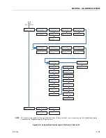
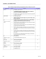
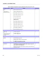
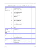
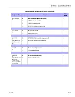
ENGINE SHUTDOWN:
7
0
1
DISABLED: No engine shutdown.
ENABLED: Shutdown engine when coolant temperature is greater than 110 deg. C or the oil
pressure is less than 8 PSI.
1
TILT:
8*
* Certain market selections will
limit tilt options and alter
default setting.
Note: Any of the selections above
will light the tilt lamp when a
tilted condition occurs and will
sound the platform alarm when
the machine is also above eleva-
tion.
1
2
3
4
5
5 DEGREES: Reduces the maximum speed of all boom functions to creep when tilted more
than 5 degrees and above elevation; also reduces drive speed to creep.
4 DEGREES: Reduces the maximum speed of all boom functions to creep when tilted more than 4 degrees
and above elevation; also reduces drive speed to creep.
3 DEGREES: Reduces the maximum speed of all boom functions to creep when tilted more than 3 degrees
and above elevation; also reduces drive speed to creep.
4 D CUT: Reduces the maximum speed of all boom functions to creep when tilted more than 4
degrees and above elevation; also disallows tower lift up, tower telescope out, drive, main telescope out
and main lift up.
3 D CUT: Reduces the maximum speed of all boom functions to creep when tilted more than 3
degrees and above elevation; also disallows tower lift up, tower telescope out, drive, main telescope out
and main lift up.
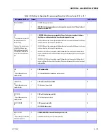
1
JIB:
9*
* Only visible under certain
model selections.
0
1
NO: No jib installed.
YES: Jib installed which has up and down movements only.
0
4 WHEEL STEER:
10*
* Only visible under certain
model selections.
0
1
NO: No four-wheel steer installed.
YES: Four-wheel steer installed.
0
SOFT TOUCH:
11*
* Only visible under certain
model selections.
0
1
NO: No soft touch system installed.
YES: Soft touch system installed.
0
GEN SET/WELDER:
12
0
1
NO: No generator installed.
BELT DRIVE: Belt driven setup.
0
GEN SET CUTOUT:
13*
* Only visible if Gen Set / Welder
Menu selection is not 0.
0
1
MOTION ENABLED: Motion enabled when generator is ON.
MOTION CUTOUT: Motion cutout in platform mode only.
0
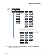
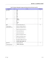
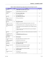
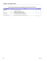
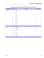
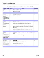
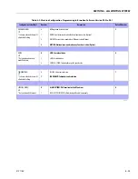
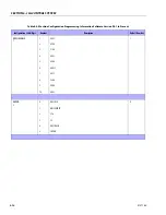
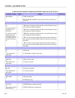
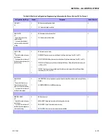
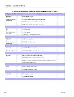
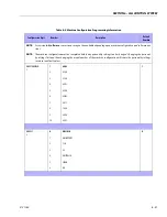
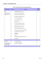
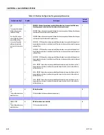
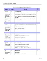
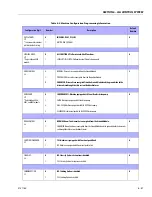
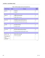
Table 6-3. Machine Configuration Programming Information Software Version P5.3 to P6.1
Configuration Label/Digit
Number
Description
Default Number
Summary of Contents for 740AJ
Page 2: ......
Page 55: ...SECTION 3 CHASSIS TURNTABLE 3121160 3 3 This page left blank intentionally...
Page 116: ...SECTION 3 CHASSIS TURNTABLE 3 64 3121160 Figure 3 44 Swing Hub Prior to SN 0300074383...
Page 203: ...SECTION 3 CHASSIS TURNTABLE 3121160 3 151 Figure 3 77 EFI Component Location...
Page 206: ...SECTION 3 CHASSIS TURNTABLE 3 154 3121160 Figure 3 78 ECM EPM Identification ECM EPM...
Page 224: ...SECTION 3 CHASSIS TURNTABLE 3 172 3121160 Figure 3 83 Deutz EMR 2 Troubleshooting Flow Chart...
Page 228: ...SECTION 3 CHASSIS TURNTABLE 3 176 3121160 Figure 3 87 EMR 2 Engine Plug Pin Identification...
Page 229: ...SECTION 3 CHASSIS TURNTABLE 3121160 3 177 Figure 3 88 EMR 2 Vehicle Plug Pin Identification...
Page 230: ...SECTION 3 CHASSIS TURNTABLE 3 178 3121160 Figure 3 89 EMR2 Fault Codes Sheet 1 of 5...
Page 231: ...SECTION 3 CHASSIS TURNTABLE 3121160 3 179 Figure 3 90 EMR2 Fault Codes Sheet 2 of 5...
Page 232: ...SECTION 3 CHASSIS TURNTABLE 3 180 3121160 Figure 3 91 EMR2 Fault Codes Sheet 3 of 5...
Page 233: ...SECTION 3 CHASSIS TURNTABLE 3121160 3 181 Figure 3 92 EMR2 Fault Codes Sheet 4 of 5...
Page 234: ...SECTION 3 CHASSIS TURNTABLE 3 182 3121160 Figure 3 93 EMR2 Fault Codes Sheet 5 of 5...
Page 303: ...SECTION 4 BOOM PLATFORM 3121160 4 31 Figure 4 20 Rotator Assembly HELAC...
Page 460: ...SECTION 5 BASIC HYDRAULIC INFORMATION AND SCHEMATICS 5 116 3121160 NOTES...
Page 467: ...SECTION 6 JLG CONTROL SYSTEM 3121160 6 7 Figure 6 2 ADE Block Diagram...
Page 534: ...SECTION 6 JLG CONTROL SYSTEM 6 74 3121160 NOTES...
Page 580: ...SECTION 7 BASIC ELECTRICAL INFORMATION SCHEMATICS 7 46 3121160 NOTES...
Page 581: ......

