SECTION 3 - CHASSIS & TURNTABLE
3121160
3-37
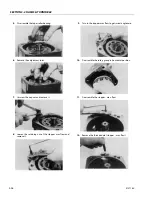
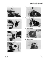
18.
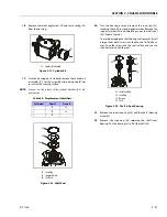
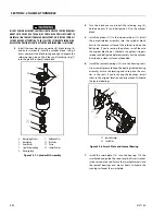
Remove minimum angle stop (29) and servo spring (30)
from the housing.
19.
Turn the housing on its side and remove the cylinder kit
assembly (31). Set the assembly aside, being careful not
to scratch the running surface.
NOTE:
Grooves on the surface of the cylinder kit identify its dis-
placement:
20.
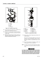
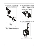
Turn the housing over and remove the snap ring (32)
retaining the shaft seal and support washer. Remove the
support washer (33) and carefully pry out the shaft seal
(34). Discard the seal.
To avoid damaging the shaft during seal removal. Install
a large sheet metal screw into the chuck of a slide ham-
mer. Drive the screw into the seal surface and use the
slide hammer to pull the seal.
21.
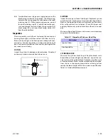
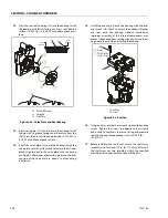
Remove the inner snap ring (35) and the shaft / bearing
assembly.
22.
Remove the snap-ring (36) retaining the shaft front
bearing. Pull the bearing (37) off of the shaft (38).
Table 3-6. Displacement Identifiers
# of Grooves
Frame L
Frame K
1
25
38
2
30
45
3
35
- -
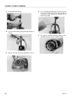
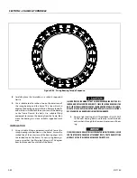
31
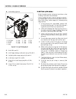
31. Cylinder Kit Assembly
Figure 3-21. Cylinder Kit
32
33
34
32. Snap Ring
33. Support Washer
34. Shaft Seal
Figure 3-22. Shaft Seal
38
37
36
35
35. Inner Snap Ring
36. Snap Ring
37. Bearing
38. Shaft
Figure 3-23. Shaft & Front Bearing
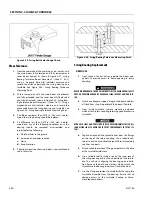
Summary of Contents for 740AJ
Page 2: ......
Page 55: ...SECTION 3 CHASSIS TURNTABLE 3121160 3 3 This page left blank intentionally...
Page 116: ...SECTION 3 CHASSIS TURNTABLE 3 64 3121160 Figure 3 44 Swing Hub Prior to SN 0300074383...
Page 203: ...SECTION 3 CHASSIS TURNTABLE 3121160 3 151 Figure 3 77 EFI Component Location...
Page 206: ...SECTION 3 CHASSIS TURNTABLE 3 154 3121160 Figure 3 78 ECM EPM Identification ECM EPM...
Page 224: ...SECTION 3 CHASSIS TURNTABLE 3 172 3121160 Figure 3 83 Deutz EMR 2 Troubleshooting Flow Chart...
Page 228: ...SECTION 3 CHASSIS TURNTABLE 3 176 3121160 Figure 3 87 EMR 2 Engine Plug Pin Identification...
Page 229: ...SECTION 3 CHASSIS TURNTABLE 3121160 3 177 Figure 3 88 EMR 2 Vehicle Plug Pin Identification...
Page 230: ...SECTION 3 CHASSIS TURNTABLE 3 178 3121160 Figure 3 89 EMR2 Fault Codes Sheet 1 of 5...
Page 231: ...SECTION 3 CHASSIS TURNTABLE 3121160 3 179 Figure 3 90 EMR2 Fault Codes Sheet 2 of 5...
Page 232: ...SECTION 3 CHASSIS TURNTABLE 3 180 3121160 Figure 3 91 EMR2 Fault Codes Sheet 3 of 5...
Page 233: ...SECTION 3 CHASSIS TURNTABLE 3121160 3 181 Figure 3 92 EMR2 Fault Codes Sheet 4 of 5...
Page 234: ...SECTION 3 CHASSIS TURNTABLE 3 182 3121160 Figure 3 93 EMR2 Fault Codes Sheet 5 of 5...
Page 303: ...SECTION 4 BOOM PLATFORM 3121160 4 31 Figure 4 20 Rotator Assembly HELAC...
Page 460: ...SECTION 5 BASIC HYDRAULIC INFORMATION AND SCHEMATICS 5 116 3121160 NOTES...
Page 467: ...SECTION 6 JLG CONTROL SYSTEM 3121160 6 7 Figure 6 2 ADE Block Diagram...
Page 534: ...SECTION 6 JLG CONTROL SYSTEM 6 74 3121160 NOTES...
Page 580: ...SECTION 7 BASIC ELECTRICAL INFORMATION SCHEMATICS 7 46 3121160 NOTES...
Page 581: ......

