SECTION 3 - CHASSIS & TURNTABLE
3-38
3121160
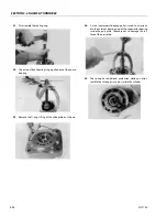
23.
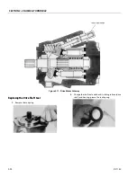
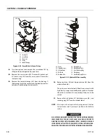
Turn housing over and remove the swashplate (39) by
lifting on the end opposite the servo lever.
24.
Remove the servo piston (40). Remove the piston seal
(41) and o-ring (42) from the servo piston. Discard the
seal and o-ring.
25.
Remove the journal bearings (43) from the housing. If
the bearings are to be reused, note the location and ori-
entation of each bearing for reassembly.
26.
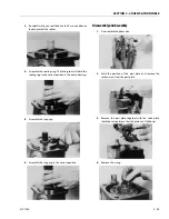
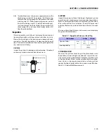
Remove pistons (44) and slipper retainer (45) from the
cylinder block (46).
The pistons are not selectively fitted, however units with
high hourly usage may develop wear patterns. Number
the pistons and bores for reassembly if they are to be
reused.
27.
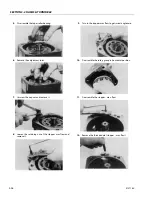
Remove the ball guide (47), hold-down pins (48), and
retaining ring (49) from the cylinder block.
NOTE:
Most repairs do not require block spring removal. Perform
this procedure only if you suspect problems with the block
spring.
RISK OF PERSONAL INJURY: COMPRESSING THE BLOCK SPRING REQUIRES
FORCE OF ABOUT 80 TO 90 LBF (350 TO 400 N). USE A PRESS SUFFICIENT TO
MAINTAIN THIS FORCE WITH REASONABLE EFFORT. ENSURE THE SPRING IS
SECURE BEFORE ATTEMPTING TO REMOVE THE SPIRAL RETAINING RING.
RELEASE THE PRESSURE SLOWLY AFTER THE RETAINING RING IS REMOVED.
41
42
40
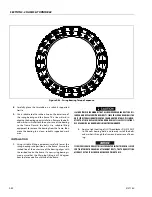
Lift here
39
43
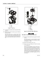
39. Swashplate
40. Servo Piston
41. Piston Seal
42. O-ring
43. Journal Bearings
Figure 3-24. Swash Plate & Servo Piston
51
50
52
53
46
49
48
47
45
44
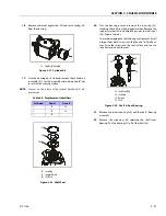
44. Piston
45. Slipper Retainer
46. Cylinder Block
47. Ball Guide
48. Holddown Pins
49. Retaining Ring
50. Block Spring Washer
51. Spiral Retaining Ring
52. Block Spring
53. Inner Block Spring Washer
Figure 3-25. Cylinder Kit Disassembly
Summary of Contents for 740AJ
Page 2: ......
Page 55: ...SECTION 3 CHASSIS TURNTABLE 3121160 3 3 This page left blank intentionally...
Page 116: ...SECTION 3 CHASSIS TURNTABLE 3 64 3121160 Figure 3 44 Swing Hub Prior to SN 0300074383...
Page 203: ...SECTION 3 CHASSIS TURNTABLE 3121160 3 151 Figure 3 77 EFI Component Location...
Page 206: ...SECTION 3 CHASSIS TURNTABLE 3 154 3121160 Figure 3 78 ECM EPM Identification ECM EPM...
Page 224: ...SECTION 3 CHASSIS TURNTABLE 3 172 3121160 Figure 3 83 Deutz EMR 2 Troubleshooting Flow Chart...
Page 228: ...SECTION 3 CHASSIS TURNTABLE 3 176 3121160 Figure 3 87 EMR 2 Engine Plug Pin Identification...
Page 229: ...SECTION 3 CHASSIS TURNTABLE 3121160 3 177 Figure 3 88 EMR 2 Vehicle Plug Pin Identification...
Page 230: ...SECTION 3 CHASSIS TURNTABLE 3 178 3121160 Figure 3 89 EMR2 Fault Codes Sheet 1 of 5...
Page 231: ...SECTION 3 CHASSIS TURNTABLE 3121160 3 179 Figure 3 90 EMR2 Fault Codes Sheet 2 of 5...
Page 232: ...SECTION 3 CHASSIS TURNTABLE 3 180 3121160 Figure 3 91 EMR2 Fault Codes Sheet 3 of 5...
Page 233: ...SECTION 3 CHASSIS TURNTABLE 3121160 3 181 Figure 3 92 EMR2 Fault Codes Sheet 4 of 5...
Page 234: ...SECTION 3 CHASSIS TURNTABLE 3 182 3121160 Figure 3 93 EMR2 Fault Codes Sheet 5 of 5...
Page 303: ...SECTION 4 BOOM PLATFORM 3121160 4 31 Figure 4 20 Rotator Assembly HELAC...
Page 460: ...SECTION 5 BASIC HYDRAULIC INFORMATION AND SCHEMATICS 5 116 3121160 NOTES...
Page 467: ...SECTION 6 JLG CONTROL SYSTEM 3121160 6 7 Figure 6 2 ADE Block Diagram...
Page 534: ...SECTION 6 JLG CONTROL SYSTEM 6 74 3121160 NOTES...
Page 580: ...SECTION 7 BASIC ELECTRICAL INFORMATION SCHEMATICS 7 46 3121160 NOTES...
Page 581: ......

