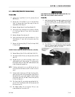
SECTION 3 - CHASSIS & TURNTABLE
3-42
3121160
RISK OF PERSONAL INJURY: COMPRESSING THE BLOCK SPRING REQUIRES
ABOUT 80 TO 90 LBF (350 TO 400 N) OF FORCE. USE A PRESS SUFFICIENT TO
MAINTAIN THIS FORCE WITH REASONABLE EFFORT. ENSURE THE SPRING IS
SECURE BEFORE ATTEMPTING TO INSTALL THE SPIRAL RETAINING RING.
RELEASE THE PRESSURE SLOWLY AFTER THE RETAINING RING IS INSTALLED.
3.
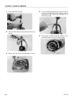
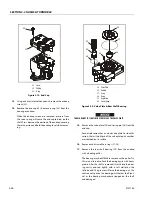
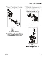
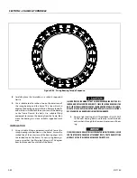
Install the inner block spring washer (4), block spring (5),
and outer washer (6) into the cylinder block. Using a
press, compress the block spring enough to expose the
retaining ring groove. Wind the spiral retaining ring (7)
into the groove in the cylinder block.
4.
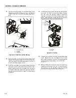
Turn the block over and install the retaining ring (8),
hold-down pins (9), and ball guide (10) to the cylinder
block.
5.
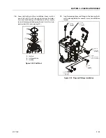
Install the pistons (11) to the slipper retainer (12). Install
the piston/retainer assembly into the cylinder block.
Ensure the concave surface of the retainer seats on the
ball guide. If you're reusing the pistons, install them to
the original block bores. Lubricate the pistons, slippers,
retainer, and ball guide before assembly. Set the cylinder
kit aside on a clean surface until needed.
6.
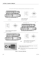
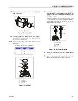
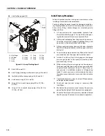
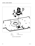
Install the journal bearings (13) into the housing seats.
Use assembly grease to keep the bearings seated during
assembly. Ensure the locating nubs drop into the cavi-
ties in the seats. If you're reusing the bearings, install
them in the original location and orientation. Lubricate
the journal bearings.
7.
Install the swashplate (14) into the housing. Tilt the
swashplate and guide the servo lever ball into its socket
in the servo piston rod. Ensure the swashplate seats into
the journal bearings and moves freely. Lubricate the
running surface of the swashplate.
7
6
5
4
8
9
10
12
11
4.
Block Spring Washer
5.
Block Spring
6.
Outer Washer
7.
Spiral Retaining Ring
8.
Retaining Ring
9.
Holddown Pins
10. Ball Guide
11. Piston
12. Slipper Retainer
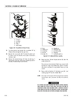
Figure 3-27. Cylinder Kit Assembly
14
13
13
13. Journal Bearings
14. Swash Plate
Figure 3-28. Swash Plate and Journal Bearing
Summary of Contents for 740AJ
Page 2: ......
Page 55: ...SECTION 3 CHASSIS TURNTABLE 3121160 3 3 This page left blank intentionally...
Page 116: ...SECTION 3 CHASSIS TURNTABLE 3 64 3121160 Figure 3 44 Swing Hub Prior to SN 0300074383...
Page 203: ...SECTION 3 CHASSIS TURNTABLE 3121160 3 151 Figure 3 77 EFI Component Location...
Page 206: ...SECTION 3 CHASSIS TURNTABLE 3 154 3121160 Figure 3 78 ECM EPM Identification ECM EPM...
Page 224: ...SECTION 3 CHASSIS TURNTABLE 3 172 3121160 Figure 3 83 Deutz EMR 2 Troubleshooting Flow Chart...
Page 228: ...SECTION 3 CHASSIS TURNTABLE 3 176 3121160 Figure 3 87 EMR 2 Engine Plug Pin Identification...
Page 229: ...SECTION 3 CHASSIS TURNTABLE 3121160 3 177 Figure 3 88 EMR 2 Vehicle Plug Pin Identification...
Page 230: ...SECTION 3 CHASSIS TURNTABLE 3 178 3121160 Figure 3 89 EMR2 Fault Codes Sheet 1 of 5...
Page 231: ...SECTION 3 CHASSIS TURNTABLE 3121160 3 179 Figure 3 90 EMR2 Fault Codes Sheet 2 of 5...
Page 232: ...SECTION 3 CHASSIS TURNTABLE 3 180 3121160 Figure 3 91 EMR2 Fault Codes Sheet 3 of 5...
Page 233: ...SECTION 3 CHASSIS TURNTABLE 3121160 3 181 Figure 3 92 EMR2 Fault Codes Sheet 4 of 5...
Page 234: ...SECTION 3 CHASSIS TURNTABLE 3 182 3121160 Figure 3 93 EMR2 Fault Codes Sheet 5 of 5...
Page 303: ...SECTION 4 BOOM PLATFORM 3121160 4 31 Figure 4 20 Rotator Assembly HELAC...
Page 460: ...SECTION 5 BASIC HYDRAULIC INFORMATION AND SCHEMATICS 5 116 3121160 NOTES...
Page 467: ...SECTION 6 JLG CONTROL SYSTEM 3121160 6 7 Figure 6 2 ADE Block Diagram...
Page 534: ...SECTION 6 JLG CONTROL SYSTEM 6 74 3121160 NOTES...
Page 580: ...SECTION 7 BASIC ELECTRICAL INFORMATION SCHEMATICS 7 46 3121160 NOTES...
Page 581: ......

