background image

Go to Discount-Equipment.com 

to order your parts

Summary of Contents for CM2033

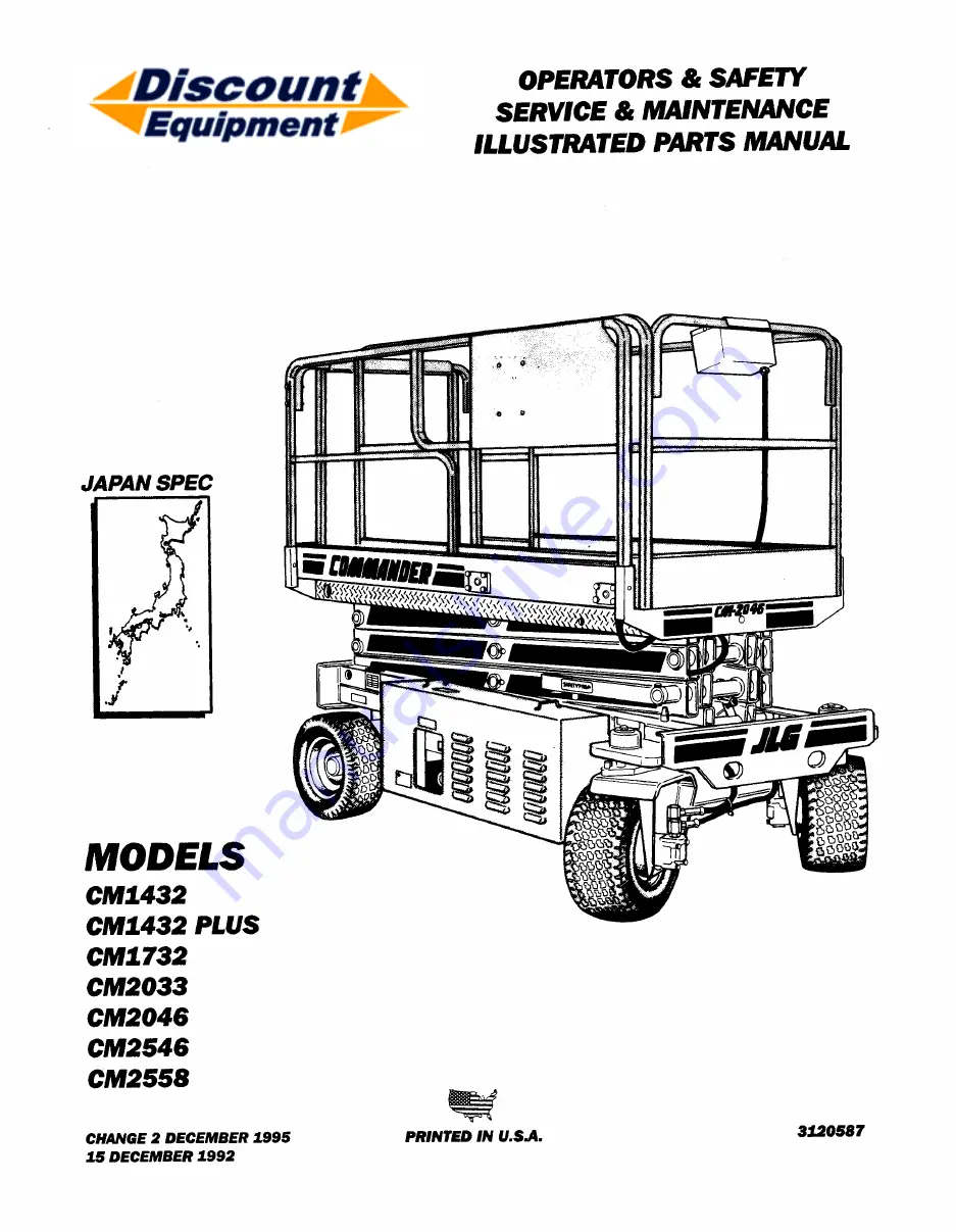
Page 1: ...61 Fu 717 485 6417 I i MODELS CM1432 CM1432 PLUS CM1732 CM2033 CM2046 CM2546 CM2558 CHANGE 2 DECEMBER 1995 15 DECEMBER 1992 OPERATORS SAFETY SERVICE MAINTENANCE ILLUSTRATED PARTS MANUAL PRINTED IN U S...

Page 2: ...e needs We sell worldwide for the brands Genie Terex JLG MultiQuip Mikasa Essick Whiteman Mayco Toro Stone Diamond Products Generac Magnum Airman Haulotte Barreto Power Blanket Nifty Lift Atlas Copco...

Page 3: ...AL FROM JLG INDUSTRIES INC A MOST IMPORTANT FACTTO REMEMBER IS THAT ANY EQUIPMENT IS ONLY AS SAFE AS THOSE WHO OPERATE IT DANGER WARNING CAUTION IMPORTANT INSTRUCTIONS AND NOTE DEFINITIONS Since safet...

Page 4: ...n the platform shall wear an approved safety belt with the lanyard at tached to the platform attachment point 6 Load limits specified by the manufacturer shall not be exceeded 7 Instruction and warnin...

Page 5: ...HYDRAULIC SYSTEM SAFETY 1 It should be particularly noted that the machines hydraulic systems operate at ex tremely high and potentially dangerous pres sures Every effort should be made to relieve an...

Page 6: ...5 13 4 7 13 4 11 13 4 13 to 13 4 15 Section 13 6 Pages 13 6 3 13 6 4 Section 13 7 Pages 13 7 1 13 7 5 13 7 10 13 7 11 Section 13 8 Page 13 8 5 December 1995 Change 2 Pages Affected Cover Revision Log...

Page 7: ...G o t o D i s c o u n t E q u i p m e n t c o m t o o r d e r y o u r p a r t s...

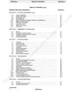
Page 8: ...2 2 2 5 Daily Functional Check 2 2 2 6 Torque Requirements 2 3 2 7 Battery Charging 2 3 SECTION 3 USER RESPONSIBILITIES AND MACHINE CONTROL 3 1 General 3 1 3 2 Personnel Training 3 1 3 3 Operating Cha...

Page 9: ...er Locations Limit Switches Major Component Weights SECTION 8 PROCEDURES 8 1 8 2 8 3 8 4 8 5 8 6 8 7 8 8 8 9 8 10 8 11 8 12 8 13 8 14 8 15 General Servicing and Maintenance Guidelines Lubrication Info...

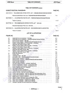
Page 10: ...orm Control Station w PQ Controller All Models Machines Built After August 1992 Grade and Sideslope Torque Chart Lubrication Chart CM1432 Lubrication Chart CM2033 CM2046 CM2546 CM2558 Serial Number Lo...

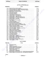
Page 11: ...ic Components and Covers Installation Control Valve Assembly Hydro Air Sizzor Arms Installation CM1432 and CM1432 Plus Sizzor Arms Installation CM1732 Platform and Handrail Installation Optional Platf...

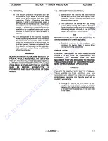
Page 12: ...OSHA RULES 1 2 DRIVING TOWING CARRYING a Before driving the machine the user must be familiar with the drive steer and stopping char acteristics This is especially important when driving in close quar...

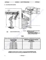
Page 13: ...ated power lines and parts VOLTAGE RANGE MINIMUM SAFE APPROACH DISTANCE Phase to Phase Feet Meters 0 to 300V AVOID CONTACT Over 300V to 50KV 10 3 Over 50KV to 200KV 15 5 Over 200KV to 350KV 20 6 Over...

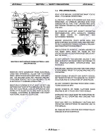
Page 14: ...OMPETENT AND AUTHORIZED PERSONS BEFORE OPERATION CHECK WORK AREA FOR BARE OVERHEAD ELECTRIC LINES MACHINE TRAF FIC SUCH AS BRIDGE CRANES HIGHWAY RAILWAY AND CONSTRUCTION EQUIPMENT PRECAUTIONS TO AVOID...

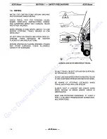
Page 15: ...LATFORM BEFORE DRIVING ON FLOORS BRIDGES TRUCKS AND OTHER SURFACES CHECK ALLOWABLE CAPACITY OF SURFACES ALWAYS LOOK IN THE DIRECTION OF TRAVEL DO NOT TRAVEL ON SOFT OR UNEVEN SURFACES AS TIPPING WILL...

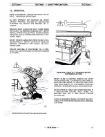
Page 16: ...EVENLY ON PLAT FORM FLOOR ENSURE MACHINE IS POSITIONED ON A FIRM LEVEL AND UNIFORM SURFACE BEFORE RAISING PLATFORM NEVER OPERATE ON SOFT OR UNEVEN SURFACES THOROUGHLY CHECK ALL CLEARANCES BEFORE POSIT...

Page 17: ...OSHA REQUIRES THAT SAFETY BELT BE ATTACHED TO THE STRUCTURE BEING ENTERED TO AVOID FALLING USE EXTREME CAUTION WHEN ENTERING OR LEAVING PLATFORM ABOVE GROUND ENTER OR EXITTHRU GATE ONLY PLAT FORM MUS...

Page 18: ...POSITIONED ON DECK DO NOT EXTEND REACH LIMITS OF THIS MACHINE WITH ADDITIONAL EQUIPMENT SUCH AS PLANKS BOXES ETC OBSERVE EXTREME CAUTION AT ALL TIMES TO PREVENT OBSTACLES FROM STRIKING OR INTER FERIN...

Page 19: ...ECURED IT IS A SAFETY VIOLATION DO NOT STEP OUTSIDE OF HANDRAILS ALWAYS ENSURE THAT POWER TOOLS ARE PROPERLY STOWED AND NEVER LEFT HANGING BY THEIR CORD FROM THE PLATFORM WORK AREA AVOID ACCUMULATION...

Page 20: ...RM COMPLETELY EMPTY OF TOOLS AND DEBRIS BEFORE CARRYING WHEN LIFTING MACHINE POSITION FORKS ONLY AT DESIGNATED AREA AT REAR OF MACHINE HAVE PLATFORM FULLY RETRACTED WHILE MACHINE IS BEING CARRIED NEVE...

Page 21: ...e first con sideration when engaging in the maintenance of equipment Always be conscious of weight Never attempt to move heavy parts without the aid of a mechanical device Do not allow heavy objects t...

Page 22: ...c tionai Check are complied with prior to putting the machine into service 2 3 DELIVERY AND PERIODIC INSPECTION Note This machine requires periodic safety and main tenance inspections by a JLG Dealer...

Page 23: ...ay painting or shot blasting to protect legibility 3 Operators Service and Parts ManuaL Ensure a copy of this manual is enclosed inthe manual storage box 4 Machine Log Ensure a machine operating recor...

Page 24: ...ability and performance of the machine 2 7 BATTERY CHARGING At the end of the work day the batteries should be charged for the next days work Position the Emer gency Stop switch to OFF Prior to chargi...

Page 25: ...ox 27 26 1 I 25 o 1A r 24 p 1 J I _ r y r t 1 I f l I ce _ Q J 23 22 21 20 J c 0 0 8 __ c 0 0 19 c p 0 0 18 c I I Ill 6 17 c 0 Oj 1 1_ 0 L 15 16 Machines Built After October 1992 Figure 2 1 Daily Walk...

Page 26: ...rop Stored securely no visible damage or missing parts 14 Wheel and Tire Assembly Left Rear Properly secured no loose or missing lug nuts no visible damage 15 Battery Charger No damage properly secure...

Page 27: ...LGSizzor 1 8 Insert A Platform Control Box Machines Built Before August 1992 Figure 2 2 Dally Walk Around Inspection CM2033 CM2046 CM2546 CM2558 Sheet 1 of 2 JLG Sizzor 24 G o t o D i s c o u n t E q...

Page 28: ...e damage placards secure and legible 15 Hydraulic Reservoir No visible damage or missing parts no evidence of leaks Recommended hydraulic fluid level on dipstick Cold fluid system shut down machine in...

Page 29: ...G o t o D i s c o u n t E q u i p m e n t c o m t o o r d e r y o u r p a r t s...

Page 30: ...ance of potential hazards in the work place with particular attention to the work to be performed 4 Proper use of all required personnel safety equipment 5 Sufficient knowledge of the mechanical opera...

Page 31: ...e needs We sell worldwide for the brands Genie Terex JLG MultiQuip Mikasa Essick Whiteman Mayco Toro Stone Diamond Products Generac Magnum Airman Haulotte Barreto Power Blanket Nifty Lift Atlas Copco...

Page 32: ...POWER SELECTOR switch in the center off posi tion power is shut off to both platform and ground controls Notes With the POWER SELECTOR switch in the OFF posi tion the key can be removed in order to In...

Page 33: ...e Drive Control Switch is a three posi tion center off toggle switch that enables the machine to travel in FORWARD or REVERSE Note When machine is equipped with non marking tires DRIVE function is cut...

Page 34: ...CH Figure 3 1 Ground Control Station CM1432 LIFTCONTROL SWITCH BATTERY CHARGER PILOTUGKT NOTE Refer to JLG Publication 3120367 for applicable battery charger information Figure 3 2 Ground Control Stat...

Page 35: ...TEER SWITCH POSITIVE t fl TRACTION SWITCH Figure 3 3 Platform Control Station w o PQ Controller All Models Machines Built Before August 1992 Figure 3 4 Platform Control Station w PQ Controller All Mod...

Page 36: ...3 5 Platform Control Station w o PQ Controller All Models Machines Built After August 1992 Figure 3 6 Platform Control Station w PQ Controller All Models Machines Built After August 1992 3 6 JLGSizzor...

Page 37: ...RD Table 3 1 Control Panel Sy mbols Sheet 1 of 3 SYMBOL 1 6 I il DANGER II t 5 FUNCTION EMERGENCY SHUT OFF EMERGENCY SWITCH DOWN EMERGENCY SWITCH UP ENGINE SPEED EXTENDABLE PLATFORM CAPACITY FACTORY M...

Page 38: ...e 3 1 Control Panel Symbols Sheet 2 of 3 SYMBOL FUNCTION MANUAL DESCENT MANUAL DESCENT KNOB MASTER SWITCH MASTER SWITCH OFF MAXIMUM PERMISSABLE PLATFORM SIDE LOAD MAXIMUM IMPORTANT PLATFORM LOAD MAXIM...

Page 39: ...ON ROUGH TERRAIN RESTRICTED DRIVE ON SLOPE SLOW STEER TIE DOWN LIFT Table 3 1 Control Panel Symbols Sheet 3 of 3 SYMBOL leJI FUNCTION TILT TWO WHEEL DRIVE FOUR WHEEL DRIVE TRAVERSING PLATFORM CAPACIT...

Page 40: ...G o t o D i s c o u n t E q u i p m e n t c o m t o o r d e r y o u r p a r t s...

Page 41: ...ydraulic motors and cylinders for the various machine mo tions The hydraulic components are controlled by electrically activated hydraulic valves using switches and control levers The speeds of func t...

Page 42: ...WERED ONLY THE WARNING LIGHT IS ILLUMINATED Note Some machines built before August 1992 and all machines built after August 1992are equipped with an ENABLEswitch on the side ofthe platform control box...

Page 43: ...ch will return to the center off position and the wheels will remain in the previously selected position To return the wheels to the straightened position the switch must be activated in the opposite...

Page 44: ...ch to REVERSE and hold for duration of travel If machine is equipped with Enable switch Enable switch must be depressed before activating DRIVE func tion 4 If machine is equipped with a PQ control ler...

Page 45: ...at the rear of the frame are provided On models CM2046 CM2546 and CM2558 four tie down eyes are provided in the frame two at the front of the frame and two at the rear of the frame WARNING USE TIE DO...

Page 46: ...G o t o D i s c o u n t E q u i p m e n t c o m t o o r d e r y o u r p a r t s...

Page 47: ...tires are made from a special compound that unlike regular tires will not leave black skid marks on floors and other surfaces 5 9 ROTATING BEACON An amber rotating beacon is installed on the machine p...

Page 48: ...G o t o D i s c o u n t E q u i p m e n t c o m t o o r d e r y o u r p a r t s...

Page 49: ...gency Stop Switch This large red button is located on the platform control box and when depressed it will imme diately stop the machine WARNING CHECK MACHINE DAILY TO MAKE SURE EMER GENCY STOP BUTTON...

Page 50: ...forktruck of suitable capacity or equivalent equipment should be placed und r the elevated side of the chassis with a crane or other suitable lifting equipment used to lift the plat form while the ch...

Page 51: ...s Tires Standard CM1432 4 00 x 8 2 5 Solid Rib Standard CM2033 CM2046 CM2546 CM2558 5 x 8 3 75 Solid Rib Optional All Models 5 x 8 3 75 Solid Non Marking Hydraulic Filter Inline All Models Return Bypa...

Page 52: ...peration and will almost completely dissipate from the hydraulic system over a several month period of time When cold weather is past it may be necessary to drain and refill the hydraulic system to ri...

Page 53: ...75 18870 683 14 2 2225 1 2929 14697 65 48 79 20775 751 1 8 2 5400 1 5392 17509 89 66 111 23360 1024 12 2 5400 1 6840 19142 97 74 116 27080 1138 1 1 8 7 2 8575 1 9380 19187 111 83 113 31162 1457 12 2...

Page 54: ...RING PLATFORM TO BE ELEVATED 7 4 Notes 1 Be sure to lubricate like items on each side of machine 2 Recommended lubricating intervals are based on normal use If machine is subjected to severe operating...

Page 55: ...hours of operation then every 250 hours thereafter 50 N A 50 N A 2000 N A 50 N A TO AVOID PERSONAL INJURY USE SAFETY PROP FOR ALL MAINTENANCE REQUIRING PLATFORM TO BE ELEVATED Notes 1 Be sure to lubri...

Page 56: ...is damaged or missing the machine serial number is stamped on the right front of the frame near the steering spindle and bushing 7 9 LIMIT SWITCHES The machines are equipped with the following limit s...

Page 57: ...I 11 I 1 tl It 1 t I t t J I l LUJ o I I 1 1 _______________________ IIUI D NUMBER PLATE Figure 7 4 Serial Number Locations CM1432 JLG Sizzor JLGSizzor 7 7 G o t o D i s c o u n t E q u i p m e n t c...

Page 58: ...UMBER PLATE SECTION 7 SPECIFICATIONS STAMPED SERIAL NUMBER Figure 7 5 Serial Number Locations CM2033 CM3046 CM2546 CM2558 JLG Sizzor JLGSizzor G o t o D i s c o u n t E q u i p m e n t c o m t o o r d...

Page 59: ...nd filters are provided to keep air fuel and oil supplies clean how ever these items must be maintained on a scheduled basis in order to function properly 2 At any time when air fuel or oil lines are...

Page 60: ...rain and flush the en tire system 2 Disassemble and reassemble parts on clean work surface Clean all metal parts with non flammable cleaning solvent Lubricate components as required to aid assembly I...

Page 61: ...e needs We sell worldwide for the brands Genie Terex JLG MultiQuip Mikasa Essick Whiteman Mayco Toro Stone Diamond Products Generac Magnum Airman Haulotte Barreto Power Blanket Nifty Lift Atlas Copco...

Page 62: ...inants from the service container Al ways clean the mesh element of the filter and replace the cartridge any time the system oil is changed 3 While the unit is shut down a good preventive maintenance...

Page 63: ...nerally as an integral part of the system valve bank Relief pressures are set slightly higher than the load requirement with the valve divert ing excess pump delivery back to the reservoir when operat...

Page 64: ...utions activate hydraulic system WARNING WHEN WORKING ON THE LIFT CYLINDER RAISE THE PLATFORM COMPLETELY AND SUP PORT THE PLATFORM USING A SUITABLE OVERHEAD LIFTING DEVICE DO NOT FULLY EXTEND LIFT CYL...

Page 65: ...ry hydraulic power source to the cylinder port block fitting WARNING DO NOT FULLVEXTEND LIFT CYLINDER TO END OF STROKE RETRACT CYLINDER SLIGHTLY TO AVOID TRAPPING PRESSURE 2 Operate the hydraulic powe...

Page 66: ...tion and excessive wear Replace as necessary 14 Inspect travel limiting collar or spacer for burrs and sharp edges If necessary dress inside diameter surface with Scotch Brite or equivalent 15 If appl...

Page 67: ...der Ensure that the piston loading o ring and seal ring are not damaged or dislodged 13 Continue pushing the rod into the barrel until the cylinder head gland can be in serted into the barrel cylinder...

Page 68: ...move the cylinder rod from the holding fixture b Cleaning and Inspection 1 Clean all parts thoroughly in an approved cleaning solvent JLG Sizzor 2 Inspect the cylinder rod for scoring taper ing ovalit...

Page 69: ...ER BARREL SURFACES 12 Install the compression spring 1 on the piston end of the cylinder rod With the barrel clamped securely and while ade quately supporting the rod insert the pis ton end into the b...

Page 70: ...H ADJUSTMENT a High Drive Cut Out Limit Switch The high drive cut out limit switch is located on the left side of the frame of the machine The switch is activated when the platform is raised above the...

Page 71: ...ents Tow Valve PROCEDURES JLG Sizzor b Main Relief Adjustment Note Machines built after June 1993 are equipped with a separate Lift relief valve On these machines before adjusting main relief turn the...

Page 72: ...tment Brake Apply Speed Adjustment P1 Adjust to 2700 PSI Lift Relief After June 1993 Refer to Paragraph 8 14 c Hi Drive Kick Out Adjustment Adjust to 1100 PSI Gauge Port 2 G2 Gauge Port 1 G1 Steer Rel...

Page 73: ...ons that may pertain to this type of equipment nor should the lists be considered as all inclusive Variances in interval times may occur due to climate and or conditions and depending on the location...

Page 74: ...ubing 1 5 7 Hydraulic Oil Tank 3 5 4 8 Hydraulic Tank Breather 6 14 9 Lift Cylinder 1 12 5 6 13 4 10 Limit Switch 1 7 11 Placards and Decals 1 2 12 Wheel and Tire Assemblies 1 8 9 13 Drive Motors 1 5...

Page 75: ...G o t o D i s c o u n t E q u i p m e n t c o m t o o r d e r y o u r p a r t s...

Page 76: ...entered in the hydraulic and electrical systems For this reason every effort has been made to ensure that all likely problems in these areas are given the fullest possibletreatment In the remaining ma...

Page 77: ...functioning properly Lift cylinder not functioning properly Motor Pump does not respond when LIFT control switch is moved to DOWN position No electrical signal being sent to LIFT DOWN control valve J...

Page 78: ...Worn seals in lift cylinder Cylinder not functioning properly Manual lowering valve not functioning properly Worn seals in lift cylinder Holding valve on lift cylinder not functioning properly Damage...

Page 79: ...perly Brake cylinder not functioning properly Motor Pump will not respond when DRIVE control is moved to FORWARD position No electrical signal being sent to the Drive valve cartridge See Machine will...

Page 80: ...e Ensure proper connection of wires Using suitable test meter perform continuity test on wiring between switches Repair or replace wires as necessary Replace switch Ensure proper connection of wire at...

Page 81: ...teer cylinder not functioning properly Wiring on control switch is damaged Wiring on solenoid valve damaged Coil in solenoid damaged Bent cylinder rod Damaged steer linkage Crossover relief valve set...

Page 82: ...unctioning properly Leak in component line or fitting Scored valve spool scored cylinder Sticking or binding valve cartridge piston rod etc Hydraulic oil not at operating temperature JLGsizzQr JLGSizz...

Page 83: ...tch not functioning properly No voltage supplied to electric motor start relay from EMERGENCY STOP switch No voltage input at terminal strip No voltage present at circuit breaker Defective circuit bre...

Page 84: ...tion or damage Repair or replace wire as necessary Unplug control box harness from platform receptacle Check wire from applicable pin in plug to control box EMERGENCY STOP switch for proper cohnection...

Page 85: ...not hold a charge Damaged wiring on control switch Control switch not functioning properly Pump motor relay not functioning properly Pump motor not functioning properly JLG Sizzor JLGSizzor REMEDY Rep...

Page 86: ...e needs We sell worldwide for the brands Genie Terex JLG MultiQuip Mikasa Essick Whiteman Mayco Toro Stone Diamond Products Generac Magnum Airman Haulotte Barreto Power Blanket Nifty Lift Atlas Copco...

Reviews: