SECTION 3 - CHASSIS, PLATFORM, & SCISSOR ARMS
3-48
31215923
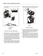
BALL GUIDE AND SLIPPER RETAINER
Inspect the ball guide and slipper retainer for damage,
discoloration, or excessive wear. A discolored ball guide
or slipper retainer indicates excessive heat. Do not
reuse.
VALVE PLATE
The condition of the valve plate is critical to the effi-
ciency of the motor. Inspect the valve plate surfaces
carefully for excessive wear, grooves, or scratches.
Replace or resurface grooved or scratched valve plates.
Measure the valve plate thickness and replace if worn
beyond the minimum specification. Valve plates may be
resurfaced to the specifications shown in the drawing,
provided resurfacing will not reduce the thickness
below the minimum specification.
SWASHPLATE AND JOURNAL BEARINGS
Inspect the running face, servo ball-joint, and swash-
plate journal surfaces for damage or excessive wear.
Some material transfer may appear on these surfaces
and is acceptable providing the surface condition meets
specifications shown. Measure the swashplate thickness
from the journals to the running face. Replace swash-
plate if damaged or worn beyond minimum specifica-
tion. Replace swashplate if the difference in thickness
from one side to the other exceeds specification.
Inspect the journal bearings for damage or excessive
wear. Replace journal bearings if scratched, warped, or
excessively worn. The polymer wear layer must be
smooth and intact.
SHAFT BEARINGS
Inspect bearings for excessive wear or contamination.
Rotate the bearings while feeling for uneven move-
ment. Bearings should spin smoothly and freely.
Replace bearings that appear worn or do not rotate
smoothly.
SHAFT
Inspect the motor shaft. Look for damage or excessive
wear on the output and block splines. Inspect the bear-
ing surfaces and sealing surface. Replace shafts with
damaged or excessively worn splines, bearing surfaces,
or sealing surfaces.
Slipper retainer
Ball guide
3.83 mm [0.151 in] min.
0.025 mm
[0.001 in]
0.0076 mm
[0.00030 in]
convex max
LV
25.8 mm
[1.015 in]
24.6 mm
[0.969 in]
KV
Thickness equality
side to side:
0.05 mm [0.002 in]
0.0025 mm
[0.0001 in]
Summary of Contents for ERT2669
Page 2: ......
Page 4: ...INTRODUCTION A 2 31215923 REVISON LOG Original Issue A January 08 2021...
Page 12: ...viii 31215923 TABLE OF CONTENTS...
Page 40: ...SECTION 1 SPECIFICATIONS 1 22 31215923...
Page 58: ...SECTION 2 GENERAL 2 18 31215923...
Page 187: ...SECTION 4 BASIC HYDRAULIC INFORMATION SCHEMATICS 31215923 4 11...
Page 206: ...SECTION 4 BASIC HYDRAULIC INFORMATION SCHEMATICS 4 30 31215923...
Page 225: ...SECTION 4 BASIC HYDRAULIC INFORMATION SCHEMATICS 31215923 4 49...
Page 242: ...SECTION 4 BASIC HYDRAULIC INFORMATION SCHEMATICS 4 66 31215923...
Page 307: ...SECTION 5 JLG CONTROL SYSTEM 31215923 5 65...
Page 334: ...SECTION 6 LSS SETUP CALIBRATION SERVICE 6 12 31215923...
Page 362: ...SECTION 7 GENERAL ELECTRICAL INFORMATION SCHEMATICS 7 28 31215923...
Page 374: ...SECTION 7 GENERAL ELECTRICAL INFORMATION SCHEMATICS 7 40 31215923...
Page 375: ......


