SECTION 3 - CHASSIS, PLATFORM, & SCISSOR ARMS
3-52
31215923
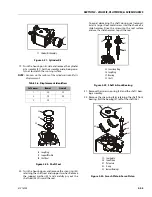
bearing surface is 0.08 ±0.01 in (2 ±0.25 mm) above
endcap surface.
13. Install timing pin (23) into its bore in the endcap.
Install the pin with its groove facing toward or away
from the shaft. Press the pin until the end protrudes
0.12 ±0.01 in (3 ±0.25 mm) above endcap surface.
14. Install the valve plate (24) onto the endcap. Install
the valve plate with the yellow surface toward the
cylinder block. Align the slot in the valve plate with
the timing pin. Apply a liberal coat of assembly
grease to the endcap side of the valve plate to keep it
in place during installation.
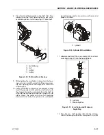
15. Install the endcap (25) onto the housing with the
endcap screws (26). Check to ensure the endcap will
properly seat onto the housing without interference.
Improper assembly of the internal components may
prevent the endcap from seating properly. Ensure
the O-rings seat properly when installing the endcap.
16. Using an 8 mm internal hex wrench, tighten the end-
cap screws. Tighten the screws in opposite corners
slowly and evenly to compress the servo spring and
properly seat the endcap. Torque endcap screws
55 ft. lbs. (75 N.m).
17. Before installing the shaft seal, ensure the shaft turns
smoothly with less than 120 in.lbs. (13.5 Nm) of force.
If the shaft does not turn smoothly within the speci-
fied maximum force, disassemble and check the unit.
18. Cover shaft splines with an installation sleeve. Install
a new shaft seal (27) with the cup side facing the
motor. Press seal into housing until it bottoms out.
23
23
22
24
3 mm
[0.12 in]
2 mm
[0.08 in]
23
22
22. Rear Shaft Bearing
23. Timing Pin
24. Valve Plate
Figure 3-32. Valve Plate and Rear Bearing
26
25
8 mm
(47-61 Nm)
35-45 ft.lbs.
25. End Cap
26. Screw
Figure 3-33. End Cap
Summary of Contents for ERT2669
Page 2: ......
Page 4: ...INTRODUCTION A 2 31215923 REVISON LOG Original Issue A January 08 2021...
Page 12: ...viii 31215923 TABLE OF CONTENTS...
Page 40: ...SECTION 1 SPECIFICATIONS 1 22 31215923...
Page 58: ...SECTION 2 GENERAL 2 18 31215923...
Page 187: ...SECTION 4 BASIC HYDRAULIC INFORMATION SCHEMATICS 31215923 4 11...
Page 206: ...SECTION 4 BASIC HYDRAULIC INFORMATION SCHEMATICS 4 30 31215923...
Page 225: ...SECTION 4 BASIC HYDRAULIC INFORMATION SCHEMATICS 31215923 4 49...
Page 242: ...SECTION 4 BASIC HYDRAULIC INFORMATION SCHEMATICS 4 66 31215923...
Page 307: ...SECTION 5 JLG CONTROL SYSTEM 31215923 5 65...
Page 334: ...SECTION 6 LSS SETUP CALIBRATION SERVICE 6 12 31215923...
Page 362: ...SECTION 7 GENERAL ELECTRICAL INFORMATION SCHEMATICS 7 28 31215923...
Page 374: ...SECTION 7 GENERAL ELECTRICAL INFORMATION SCHEMATICS 7 40 31215923...
Page 375: ......


