SECTION 3 - CHASSIS, PLATFORM, & SCISSOR ARMS
3-58
31215923
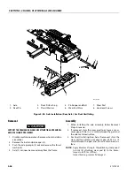
Steer Cylinder Removal
1. Disable machine operation and block all wheels. Dis-
connect, cap and label all hydraulic lines on steer cyl-
inder (8).
2. Remove the cotter pin (5), clevis pin (11) and bushing
(3) connecting cylinder rod to tie rod (10). Slide the
tie rod (10) out of the cylinder rod, capture the
washer (6) on bottom of tie rod (10).
3. Support steer cylinder. Remove flat Head clevis pin
(4) and cotter pin (5) connecting cylinder to axle.
Carefully remove cylinder. Capture the washer (6) on
bottom of cylinder.
Spindle Removal
1. Remove wheel and drive assembly prior to spindle
(9) removal.
2. Disconnect tie rod (10) from the spindle (9) by
removing the cotter pin (5) and clevis pin (11) con-
necting cylinder rod to tie rod (10). Slide the tie rod
out of the spindle (9), capture the washer (6) on bot-
tom of tie rod (10).
3. Support spindle. Remove spindle from axle by
removing cap screw (1) and washer (12) from King
Pin (7). Remove the king pin (7) and thrust bearing (2)
from axle.
Assembly
1. When assembling steer cylinder and spindle, follow
Removal Steps in reverse.
NOTE:
Apply Medium Strength Threadlocking Compound
to bolt (1). Torque to 40.56 ft. lbs. (55 Nm).
Inspect bushing, replace if damaged.
Ensure thrust bearing (2) is installed between spindle
(9) and bottom of axle.
Be certain king pin (7) is aligned and seated in the
machined groove on the axle before tightening.
NOTE:
Need to replace the thrust washer if it is worn more
than half way (0.094 or less).
Summary of Contents for ERT2669
Page 2: ......
Page 4: ...INTRODUCTION A 2 31215923 REVISON LOG Original Issue A January 08 2021...
Page 12: ...viii 31215923 TABLE OF CONTENTS...
Page 40: ...SECTION 1 SPECIFICATIONS 1 22 31215923...
Page 58: ...SECTION 2 GENERAL 2 18 31215923...
Page 187: ...SECTION 4 BASIC HYDRAULIC INFORMATION SCHEMATICS 31215923 4 11...
Page 206: ...SECTION 4 BASIC HYDRAULIC INFORMATION SCHEMATICS 4 30 31215923...
Page 225: ...SECTION 4 BASIC HYDRAULIC INFORMATION SCHEMATICS 31215923 4 49...
Page 242: ...SECTION 4 BASIC HYDRAULIC INFORMATION SCHEMATICS 4 66 31215923...
Page 307: ...SECTION 5 JLG CONTROL SYSTEM 31215923 5 65...
Page 334: ...SECTION 6 LSS SETUP CALIBRATION SERVICE 6 12 31215923...
Page 362: ...SECTION 7 GENERAL ELECTRICAL INFORMATION SCHEMATICS 7 28 31215923...
Page 374: ...SECTION 7 GENERAL ELECTRICAL INFORMATION SCHEMATICS 7 40 31215923...
Page 375: ......


