SECTION 3 - CHASSIS, PLATFORM, & SCISSOR ARMS
31215923
3-61
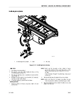
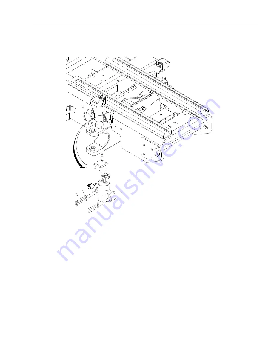
Oscillating Axle Cylinder
REMOVAL
1. Disable machine operation.
2. Disconnect, cap and label hydraulic lines on the
Oscillating Axle Cylinder (1).
3. Disconnect all the valve assembled on axle oscillat-
ing cylinder (1).
4. Remove the four bolts (2) and washers (3) connect-
ing the cylinder to the frame.
5. Carefully remove cylinder from the frame.
INSTALLATION
1. Attach cylinder to frame using four bolts (2) and
washers (3).
NOTE:
Make sure the shoulder on the cylinder is firmly
against the bottom of the mounting plates on the
frame before torquing bolts. Torque to 71.5 ft. lbs.
(97 Nm).
Apply Medium Strength Threadlocking Compound
to bolts (2).
2. Uncap and reconnect hydraulic lines to cylinder.
NOTE:
Refer to Section 4.10, Cylinder Assemblies for axle
lockout cylinder breakdown and bleeding procedure.
3. Operate oscillating axle cylinder function to ensure
proper functioning.
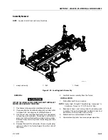
1. Oscillating Axle Cylinder
2. Bolt
3. Washer
Figure 3-41. Oscillating Axle Cylinder
2
3
1
MAF42090
Summary of Contents for ERT2669
Page 2: ......
Page 4: ...INTRODUCTION A 2 31215923 REVISON LOG Original Issue A January 08 2021...
Page 12: ...viii 31215923 TABLE OF CONTENTS...
Page 40: ...SECTION 1 SPECIFICATIONS 1 22 31215923...
Page 58: ...SECTION 2 GENERAL 2 18 31215923...
Page 187: ...SECTION 4 BASIC HYDRAULIC INFORMATION SCHEMATICS 31215923 4 11...
Page 206: ...SECTION 4 BASIC HYDRAULIC INFORMATION SCHEMATICS 4 30 31215923...
Page 225: ...SECTION 4 BASIC HYDRAULIC INFORMATION SCHEMATICS 31215923 4 49...
Page 242: ...SECTION 4 BASIC HYDRAULIC INFORMATION SCHEMATICS 4 66 31215923...
Page 307: ...SECTION 5 JLG CONTROL SYSTEM 31215923 5 65...
Page 334: ...SECTION 6 LSS SETUP CALIBRATION SERVICE 6 12 31215923...
Page 362: ...SECTION 7 GENERAL ELECTRICAL INFORMATION SCHEMATICS 7 28 31215923...
Page 374: ...SECTION 7 GENERAL ELECTRICAL INFORMATION SCHEMATICS 7 40 31215923...
Page 375: ......


