SECTION 3 - CHASSIS, PLATFORM, & SCISSOR ARMS
31215923
3-101
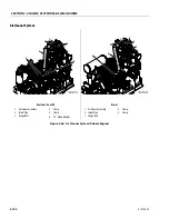
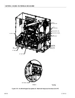
Dual Fuel - Gas/LPG
ALLOW ENGINE AND COMPONENTS TO COOL DOWN BEFORE SERVIC-
ING.
REMOVAL
1. Disable machine operation. Remove engine door &
engine cover shield.
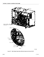
2. Disconnect, cap and label all hoses connected to
engine (1) exhaust system. Disconnect and label all
electrical wiring connected to engine (1) and exhaust
system.
3. Disconnect the O2 sensor (2) wiring. Disassemble the
upstream O2 sensor pipe (7), connecting muffler to
engine exhaust manifold, by removing the associ-
ated hardwares.
4. Disconnect the O2 sensor (2) wiring. Disassemble the
downstream O2 sensor Pipe (6), connecting muffler
to engine mount, by removing the associated hard-
wares.
INSTALLATION
1. Follow Removal Steps in reverse.
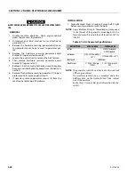
NOTE:
Torque on O2 Sensors is 28.8-36 ft. lbs. (39.1-48.9
Nm).
NOTE:
Use gasket and hardware supplied with engine to
assemble exhaust pipe to muffler. Torque to
21.7-25.3 ft. lbs. (29.3-34.3 Nm).
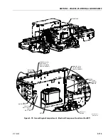
Diesel
ALLOW ENGINE AND COMPONENTS TO COOL DOWN BEFORE SERVIC-
ING.
REMOVAL
1. Disable machine operation. Remove engine door &
engine cover shield.
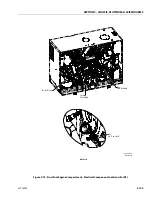
2. Disconnect, cap and label all hoses connected to
engine (1) exhaust system. Disconnect and label all
electrical wiring connected to engine (1) and exhaust
system.
3. Remove the hardware securing muffler (2) to engine
by disassembling L shape bracket (3) and other hard-
wares.
4. Supporting the muffler, Remove 4 bolts and gasket
securing muffler to engine (1).
5. Lift and remove the muffler from the machine.
6. Supporting exhaust pipe, remove the hardware
securing exhaust pipe to engine hood and engine
tray.
7. Remove the exhaust pipe.
INSTALLATION
1. Follow Removal Steps in reverse.
NOTE:
Torque for reassembling the muffler to exhaust man-
ifold 17.7-19.2 ft. lbs. (24-26 Nm)
Summary of Contents for ERT2669
Page 2: ......
Page 4: ...INTRODUCTION A 2 31215923 REVISON LOG Original Issue A January 08 2021...
Page 12: ...viii 31215923 TABLE OF CONTENTS...
Page 40: ...SECTION 1 SPECIFICATIONS 1 22 31215923...
Page 58: ...SECTION 2 GENERAL 2 18 31215923...
Page 187: ...SECTION 4 BASIC HYDRAULIC INFORMATION SCHEMATICS 31215923 4 11...
Page 206: ...SECTION 4 BASIC HYDRAULIC INFORMATION SCHEMATICS 4 30 31215923...
Page 225: ...SECTION 4 BASIC HYDRAULIC INFORMATION SCHEMATICS 31215923 4 49...
Page 242: ...SECTION 4 BASIC HYDRAULIC INFORMATION SCHEMATICS 4 66 31215923...
Page 307: ...SECTION 5 JLG CONTROL SYSTEM 31215923 5 65...
Page 334: ...SECTION 6 LSS SETUP CALIBRATION SERVICE 6 12 31215923...
Page 362: ...SECTION 7 GENERAL ELECTRICAL INFORMATION SCHEMATICS 7 28 31215923...
Page 374: ...SECTION 7 GENERAL ELECTRICAL INFORMATION SCHEMATICS 7 40 31215923...
Page 375: ......


