SECTION 3 - CHASSIS, PLATFORM, & SCISSOR ARMS
31215923
3-103
Dual Fuel - Gas/LPG
ALLOW ENGINE AND COMPONENTS TO COOL DOWN BEFORE SERVIC-
ING.
REMOVAL
1. Disable machine operation. Remove engine door &
engine cover shield.
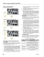
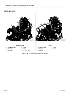
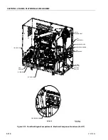
2. Loosen the clamp (4) and (5) attaching the intake
pipe (2) to the air cleaner assembly (1) and engine
intake manifold. Disconnect the intake pipe (2) from
the air cleaner assembly (1) and remove the com-
plete intake pipe (2) from the engine assembly.
3. To remove the air cleaner assembly (1) from the
engine assembly, loosen the flange bolts (4) and slide
the air cleaner assembly (1) back and down for
removal.
NOTE:
The filter element can be removed from the air
cleaner by releasing the latches on the end of the air
cleaner. Replace filter element as needed. See Section
2.5, Service Maintenance Components.
INSTALLATION
1. Follow Removal Steps in reverse.
NOTE:
Torque to 2.9-3.7 ft. lbs. (4.0-5.0 Nm). Ensure clamp is
not positioned on air cleaner tube bead.
NOTE:
When trying to remove the air cleaner assembly.
DO NOT release the latches on the end and remove
the end cap. Also no need to remove the flange hard-
ware to remove the air cleaner assembly. Loosen the
clamp and slide it out.
Diesel
ALLOW ENGINE AND COMPONENTS TO COOL DOWN BEFORE SERVIC-
ING.
REMOVAL
1. Disable machine operation. Remove engine door &
engine cover shield.
2. Loosen the clamp (4) and (5) attaching the intake
pipe (2) to the air cleaner assembly (1) and engine
intake manifold. Disconnect the intake pipe (2) from
the air cleaner assembly (1) and remove the com-
plete intake pipe (2) from the engine assembly.
3. To remove the air cleaner assembly (1) from the
engine assembly, loosen the flange bolts (4) and slide
the air cleaner assembly (1) back and down for
removal.
NOTE:
The filter element can be removed from the air
cleaner by releasing the latches on the end of the air
cleaner. Replace filter element as needed. See Section
2.5, Service Maintenance Components.
INSTALLATION
1. Follow Removal Steps in reverse.
NOTE:
Torque to 3.4-4.8 ft. lbs. (4.6-6.6 Nm). Ensure clamp is
not positioned on air cleaner tube bead.
NOTE:
When trying to remove the air cleaner assembly.
DO NOT release the latches on the end and remove
the end cap. Also no need to remove the flange hard-
ware to remove the air cleaner assembly. Loosen the
clamp and slide it out.
Summary of Contents for ERT2669
Page 2: ......
Page 4: ...INTRODUCTION A 2 31215923 REVISON LOG Original Issue A January 08 2021...
Page 12: ...viii 31215923 TABLE OF CONTENTS...
Page 40: ...SECTION 1 SPECIFICATIONS 1 22 31215923...
Page 58: ...SECTION 2 GENERAL 2 18 31215923...
Page 187: ...SECTION 4 BASIC HYDRAULIC INFORMATION SCHEMATICS 31215923 4 11...
Page 206: ...SECTION 4 BASIC HYDRAULIC INFORMATION SCHEMATICS 4 30 31215923...
Page 225: ...SECTION 4 BASIC HYDRAULIC INFORMATION SCHEMATICS 31215923 4 49...
Page 242: ...SECTION 4 BASIC HYDRAULIC INFORMATION SCHEMATICS 4 66 31215923...
Page 307: ...SECTION 5 JLG CONTROL SYSTEM 31215923 5 65...
Page 334: ...SECTION 6 LSS SETUP CALIBRATION SERVICE 6 12 31215923...
Page 362: ...SECTION 7 GENERAL ELECTRICAL INFORMATION SCHEMATICS 7 28 31215923...
Page 374: ...SECTION 7 GENERAL ELECTRICAL INFORMATION SCHEMATICS 7 40 31215923...
Page 375: ......


