SECTION 3 - CHASSIS, PLATFORM, & SCISSOR ARMS
3-34
31215923
Hub-Spindle Disassembly
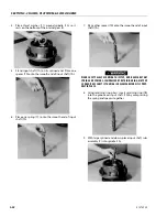
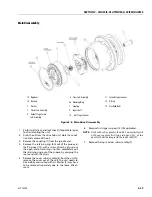
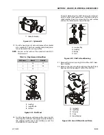
1. 1.Place the hub-spindle assembly on the bench with
Spindle (1A) end down.
2. Remove retaining ring (1J) with appropriate tool.
3. Remove spacer (1N).
4. Remove "A" position bearing cone (1C) from bearing
cup (1D) in hub (1G).
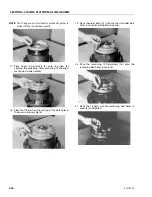
5. Lift hub (1G) from spindle (1A). Remove boot seal
(1Q) from hub (1G) (if applicable).
6. Press 9 studs (1H) out from the hub (1G). Locate hub
(1G) on seal (1B) end (if necessary).
7. Remove seal (1B) from hub (1G).
NOTE:
The Seal (1B) should NOT be reused when reassem-
bling the unit.
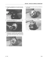
8. Remove "B" position bearing cone (1E) from hub
(1G).
9. Using a soft steel rod, knock both the bearing cups
(1D) out of hub (1G).
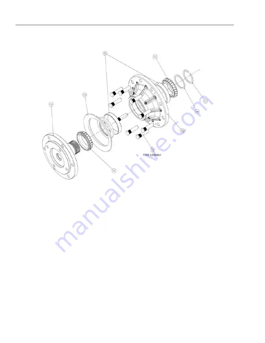
1A. Spindle
1B. Seal
1C. Bearing Cone
1D. Bearing Cup
1E. Bearing Cone
1G. Hub
1H. Stud
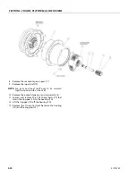
Figure 3-11. Hub-Spindle Disassembly
Summary of Contents for ERT2669
Page 2: ......
Page 4: ...INTRODUCTION A 2 31215923 REVISON LOG Original Issue A January 08 2021...
Page 12: ...viii 31215923 TABLE OF CONTENTS...
Page 40: ...SECTION 1 SPECIFICATIONS 1 22 31215923...
Page 58: ...SECTION 2 GENERAL 2 18 31215923...
Page 187: ...SECTION 4 BASIC HYDRAULIC INFORMATION SCHEMATICS 31215923 4 11...
Page 206: ...SECTION 4 BASIC HYDRAULIC INFORMATION SCHEMATICS 4 30 31215923...
Page 225: ...SECTION 4 BASIC HYDRAULIC INFORMATION SCHEMATICS 31215923 4 49...
Page 242: ...SECTION 4 BASIC HYDRAULIC INFORMATION SCHEMATICS 4 66 31215923...
Page 307: ...SECTION 5 JLG CONTROL SYSTEM 31215923 5 65...
Page 334: ...SECTION 6 LSS SETUP CALIBRATION SERVICE 6 12 31215923...
Page 362: ...SECTION 7 GENERAL ELECTRICAL INFORMATION SCHEMATICS 7 28 31215923...
Page 374: ...SECTION 7 GENERAL ELECTRICAL INFORMATION SCHEMATICS 7 40 31215923...
Page 375: ......


