SECTION 3 - CHASSIS, PLATFORM, & SCISSOR ARMS
3-80
31215923
REMOVAL
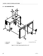
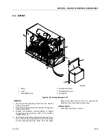
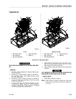
1. To remove one or more batteries from the machine,
first disconnect the positive (+) battery cable (1) from
the forward most battery connected to the main
contactor relay.
2. Disconnect the negative (-) battery cable (2) from the
forward most battery connected to the main contac-
tor relay.
3. Remove all interconnected battery cables from the
machine.
4. Remove the J-bolt (5) by removing hardware secur-
ing battery secure top plate (3) to battery tray.
Remove the battery secure top plate (3). Repeat
same for other plate.
5. Battery (4) can be removed from the tray.
1.
Battery Positive Terminal
2.
Battery Negative Terminal
3.
Battery Secure Top Plate
4.
Battery
5.
J-bolt
Figure 3-59. Battery Removal - ERT
MAF43900B
2
1
3
4
4
3
5
5
Summary of Contents for ERT2669
Page 2: ......
Page 4: ...INTRODUCTION A 2 31215923 REVISON LOG Original Issue A January 08 2021...
Page 12: ...viii 31215923 TABLE OF CONTENTS...
Page 40: ...SECTION 1 SPECIFICATIONS 1 22 31215923...
Page 58: ...SECTION 2 GENERAL 2 18 31215923...
Page 187: ...SECTION 4 BASIC HYDRAULIC INFORMATION SCHEMATICS 31215923 4 11...
Page 206: ...SECTION 4 BASIC HYDRAULIC INFORMATION SCHEMATICS 4 30 31215923...
Page 225: ...SECTION 4 BASIC HYDRAULIC INFORMATION SCHEMATICS 31215923 4 49...
Page 242: ...SECTION 4 BASIC HYDRAULIC INFORMATION SCHEMATICS 4 66 31215923...
Page 307: ...SECTION 5 JLG CONTROL SYSTEM 31215923 5 65...
Page 334: ...SECTION 6 LSS SETUP CALIBRATION SERVICE 6 12 31215923...
Page 362: ...SECTION 7 GENERAL ELECTRICAL INFORMATION SCHEMATICS 7 28 31215923...
Page 374: ...SECTION 7 GENERAL ELECTRICAL INFORMATION SCHEMATICS 7 40 31215923...
Page 375: ......


