SECTION 3 - CHASSIS, PLATFORM, & SCISSOR ARMS
31215923
3-95
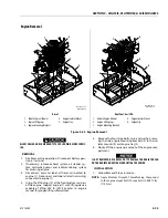
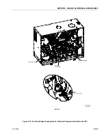
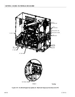
Engine Removal
ALLOW ENGINE AND COMPONENTS TO COOL DOWN BEFORE SERVIC-
ING.
REMOVAL
1. Disable machine operation. Disconnect battery posi-
tive (+) terminal.
2. If necessary, remove exhaust system, air cleaner sys-
tem, hydraulic pumps and radiator cooling system
for accessing engine.
3. Disconnect, cap and label all hoses connected to
engine (1). Disconnect and label all electrical wiring
connected to engine (1).
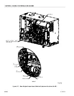
4. Using the lifting lugs (2) at the front and rear corners
of the engine, support engine (1) with lifting device
capable of lifting 500 lb (227 kg) (refer to engine
manual for proper lifting information).
5. Remove the four large bolts, nuts, and washers secur-
ing the side engine mounting brackets (3) to the iso-
lator mounts (4) and engine tray (5).
6. Slowly lift the engine up and out of the engine com-
partment.
IF NOT REMOVED, BE CAREFUL NOT TO DAMAGE THE RADIATOR FAN
ON THE RADIATOR HOUSING WHEN LIFTING THE ENGINE.
INSTALLATION
1. Follow Removal Steps in reverse.
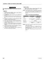
NOTE:
Apply Medium Strength Threadlocking Compound
to the engine mount bolts. Torque bolts to 84.8 ft. lbs.
(115 Nm).
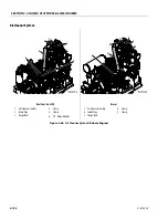
Diesel
Dual Fuel - Gas/LPG
1.
Kubota Engine (Shown)
2.
Engine Lifting Lugs
3.
Engine Mounting Brackets
4.
Engine Isolator Mount
5.
Engine Tray
1.
Kubota Engine (Shown)
2.
Engine Lifting Lugs
3.
Engine Mounting Brackets
4.
Engine Isolator Mount
5.
Engine Tray
Figure 3-63. Engine Removal
MAF42300C
1001255872-C
3
4
5
1
2
2
MAF42310C
1001256031-C
3
4
5
1
2
2
Summary of Contents for ERT2669
Page 2: ......
Page 4: ...INTRODUCTION A 2 31215923 REVISON LOG Original Issue A January 08 2021...
Page 12: ...viii 31215923 TABLE OF CONTENTS...
Page 40: ...SECTION 1 SPECIFICATIONS 1 22 31215923...
Page 58: ...SECTION 2 GENERAL 2 18 31215923...
Page 187: ...SECTION 4 BASIC HYDRAULIC INFORMATION SCHEMATICS 31215923 4 11...
Page 206: ...SECTION 4 BASIC HYDRAULIC INFORMATION SCHEMATICS 4 30 31215923...
Page 225: ...SECTION 4 BASIC HYDRAULIC INFORMATION SCHEMATICS 31215923 4 49...
Page 242: ...SECTION 4 BASIC HYDRAULIC INFORMATION SCHEMATICS 4 66 31215923...
Page 307: ...SECTION 5 JLG CONTROL SYSTEM 31215923 5 65...
Page 334: ...SECTION 6 LSS SETUP CALIBRATION SERVICE 6 12 31215923...
Page 362: ...SECTION 7 GENERAL ELECTRICAL INFORMATION SCHEMATICS 7 28 31215923...
Page 374: ...SECTION 7 GENERAL ELECTRICAL INFORMATION SCHEMATICS 7 40 31215923...
Page 375: ......


