SECTION 3 - CHASSIS, PLATFORM, & SCISSOR ARMS
3-118
31215923
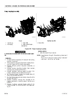
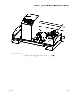
Pump Coupling Assembly
ALLOW ENGINE AND COMPONENTS TO COOL DOWN BEFORE SERVIC-
ING.
REMOVAL
1. Disable machine operation. Disconnect the battery
positive (+) terminal.
2. If required, remove gear pump from coupling hous-
ing. refer Figure 3-80. for removal procedure.
3. Remove exhaust system and pump assemblies, as
necessary.
4. Remove engine mounting brackets from coupler
housing (1) by removing hardwares.
5. Remove hardware securing coupler housing (1) to
engine. Carefully remove coupler housing (1).
6. For Dual fuel engine, remove the adapter plate (5)
along with coupler housing (1).
7. For Dual fuel engine, remove double clamp from the
coupler housing (1).
8. Remove hardware securing disc coupling (2) to
Engine Flywheel (4). carefully collect the disc cou-
pling (2).
9. Remove hardware securing engine pulley (3) to
Engine Flywheel (4). Carefully collect the engine pul-
ley (3).
INSTALLATION
1. Follow Removal Steps in reverse.
NOTE:
Apply Medium Strength Threadlocking Compound
to bolts.
Torque disc coupling and engine pulley to flywheel
bolts to 36.1 - 40.5 ft. lbs. (49 - 55 Nm).
Diesel
Dual Fuel - Gas/LPG
1.
Coupler Housing
2. Disc Coupling
3. Engine Pulley
4. Engine Flywheel/Coupler
Mounting Plate
5. Adapter Plate
Figure 3-81. Pump Coupling Assembly
MAF42360
1
2
2
3
4
MAF42560
1
5
3
4
2
2
Summary of Contents for ERT2669
Page 2: ......
Page 4: ...INTRODUCTION A 2 31215923 REVISON LOG Original Issue A January 08 2021...
Page 12: ...viii 31215923 TABLE OF CONTENTS...
Page 40: ...SECTION 1 SPECIFICATIONS 1 22 31215923...
Page 58: ...SECTION 2 GENERAL 2 18 31215923...
Page 187: ...SECTION 4 BASIC HYDRAULIC INFORMATION SCHEMATICS 31215923 4 11...
Page 206: ...SECTION 4 BASIC HYDRAULIC INFORMATION SCHEMATICS 4 30 31215923...
Page 225: ...SECTION 4 BASIC HYDRAULIC INFORMATION SCHEMATICS 31215923 4 49...
Page 242: ...SECTION 4 BASIC HYDRAULIC INFORMATION SCHEMATICS 4 66 31215923...
Page 307: ...SECTION 5 JLG CONTROL SYSTEM 31215923 5 65...
Page 334: ...SECTION 6 LSS SETUP CALIBRATION SERVICE 6 12 31215923...
Page 362: ...SECTION 7 GENERAL ELECTRICAL INFORMATION SCHEMATICS 7 28 31215923...
Page 374: ...SECTION 7 GENERAL ELECTRICAL INFORMATION SCHEMATICS 7 40 31215923...
Page 375: ......


