Outriggers
10-10
31200079
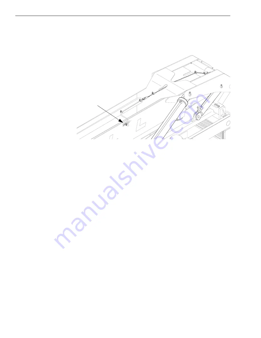
Boom Extension Proximity Switch
Description
Fig. 10-6: Boom Extension Proximity Switch
(Ref. Fig. 10-6) The boom extension proximity switch is located on the left
side of the outer boom section on machines with a 4-section boom. The
boom extend/lockout circuit is designed to increase stability of the machine
by limiting how far the boom can be extended without the outriggers down.
The system will disable the boom extend and transfer extend functions and
the warning lamp will come on when the boom is extended to specified
distance (approximately 21 feet with tilting tower or 25 feet with standard
carriage). The proximity switch then opens as it no longer senses metal. At
this point, the left and right outriggers must both be lowered to the ground
to allow the boom or transfer carriage to be extended any further.
Normally open differential pressure switches in the outrigger cylinders
close when the base end pressure exceeds the rod end pressure by
approximately 90–95 psi. When both pressure switches close, this
completes the circuit, allowing the boom and transfer carriage to be
extended, and the lamp turns off. The system is fail-safe in that it requires
an electrical signal to enable the boom to be extended beyond the
specified distance.
0
80
60
40
20
Proximity Switch
J
1146
Summary of Contents for Lull 1044C-54 II Series
Page 1: ...Service Manual Model 1044C 54 Series II 31200079 Revised July 1 2005 ...
Page 2: ......
Page 4: ...EFFECTIVITY PAGE 31200079 ii ...
Page 20: ...16 31200079 List of Tables ...
Page 22: ......
Page 34: ...ii 31200079 ...
Page 64: ...General Maintenance 3 20 31200079 ...
Page 66: ...31200079 ii ...
Page 69: ...Reference Diagrams 31200079 4 3 Diagram 4 1 Mid Inlet Hydraulic Schematic cont d NOTES ...
Page 70: ...Reference Diagrams 4 4 31200079 Diagram 4 1 Mid Inlet Hydraulic Schematic cont d NOTES ...
Page 72: ...Reference Diagrams 4 6 31200079 NOTES ...
Page 76: ...Reference Diagrams 4 10 31200079 Diagram 4 3 Electrical Schematic cont d NOTES ...
Page 77: ...Reference Diagrams 31200079 4 11 Diagram 4 3 Electrical Schematic cont d NOTES ...
Page 78: ...Reference Diagrams 4 12 31200079 ...
Page 82: ...iv 31200079 ...
Page 136: ...Supply Pressure and Return Hydraulics 5 54 31200079 ...
Page 277: ...Boom and Transfer 31200079 6 135 ...
Page 278: ...Boom and Transfer 6 136 31200079 ...
Page 281: ...31200079 iii ...
Page 282: ......
Page 322: ...Frame Tilt and Oscillation 7 40 31200079 ...
Page 324: ......
Page 344: ...ii 31200079 ...
Page 364: ......
Page 380: ...Outriggers 10 16 31200079 ...
Page 381: ......


