SECTION 3 - CHASSIS & TURNTABLE
3121200
3-71
3.18
OUTRIGGER LIMIT SWITCHES
A mechanical limit switch at each outrigger senses the outrig-
ger has been set. The control system reports status of each
outrigger through the analyzer and also displays a solid lit LED
at the ground control when set. All outriggers must be set
prior to leveling. In addition, unset outriggers are reported to
the controls system, and the machine functions will be cut
back in the event two outriggers are unset or if one outrigger
is unset and the machine is tilted (>2.0°).
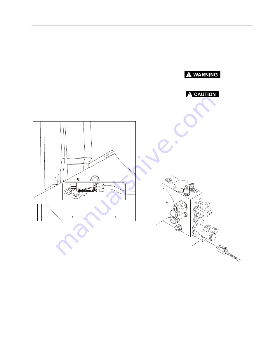
Adjustment
Adjust the limit switch position so the switch is activated when
the outriggers are fully retracted (pin to the left side of the
slot) as shown below and the switch resets when the outrig-
gers are down and set (pin to the right side of the slot).
3.19
AUTOMATIC LEVELING SENSING SYSTEM
When all outriggers are set, the system looks at the angle
reported by the bi-directional tilt sensor mounted on the
ground board. The system automatically adjusts the outrig-
gers until the chassis is level within 1.0° a compound angle
prior to allowing operating the boom above elevation.
3.20
PROCEDURE FOR RETRACTING OUTRIGGERS
USING SERVICE HARNESS (OPTIONAL)
NOTE:
Outrigger harness P/N 4923341 is an accessory that must
be purchased separately.
TIP OVER HAZARD
BEFORE RETRACTING THE OUTRIGGERS, MAKE SURE THE BOOM IS FULLY
RETRACTED, LOWERED, AND SWUNG INTO STOWED POSITION. REMOVE ALL
PERSONNEL FROM PLATFORM. REFER TO THE MACHINE OPERATION AND
SAFETY MANUAL, SECTION 6, FOR THE MANUAL DESCENT PROCEDURES. FAIL-
URE TO FOLLOW THESE INSTRUCTIONS COULD RESULT IN DEATH OR SERIOUS
INJURY.
1.
To begin the outrigger retract procedure, locate the out-
rigger retract coil wire connected to the control valve
located in the valve compartment and disconnect the
connector from coil.
2.
Utilizing the service outrigger retract harness (JLG P/N
4923341), locate the wire labeled outrigger retract and
plug into the outrigger retract connector on the control
valve.
OUTRIGGER
RETRACT
COIL
EMERGENCY
OUTRIGGER
HARNESS
Summary of Contents for T500J
Page 1: ...Service and Maintenance Manual Model T500J PN 3121200 July 25 2018 Rev I AS NZS...
Page 2: ......
Page 16: ...xii 3121200 LIST OF TABLES TABLE NO TITLE PAGE NO This page left blank intentionally...
Page 36: ...SECTION 2 GENERAL 2 8 3121200 NOTES...
Page 143: ...SECTION 3 CHASSIS TURNTABLE 3121200 3 107 Figure 3 45 Battery Charger Schematic...
Page 234: ...SECTION 5 BASIC HYDRAULIC INFORMATION SCHEMATICS 5 60 3121200 NOTES...
Page 246: ...SECTION 6 JLG CONTROL SYSTEM 6 12 3121200 Figure 6 5 System Test Flow Chart Platform Tests...
Page 304: ...SECTION 7 BASIC ELECTRICAL INFORMATION SCHEMATICS 7 32 3121200 NOTES...
Page 305: ......


