SECTION 3 - CHASSIS & TURNTABLE
3121200
3-105
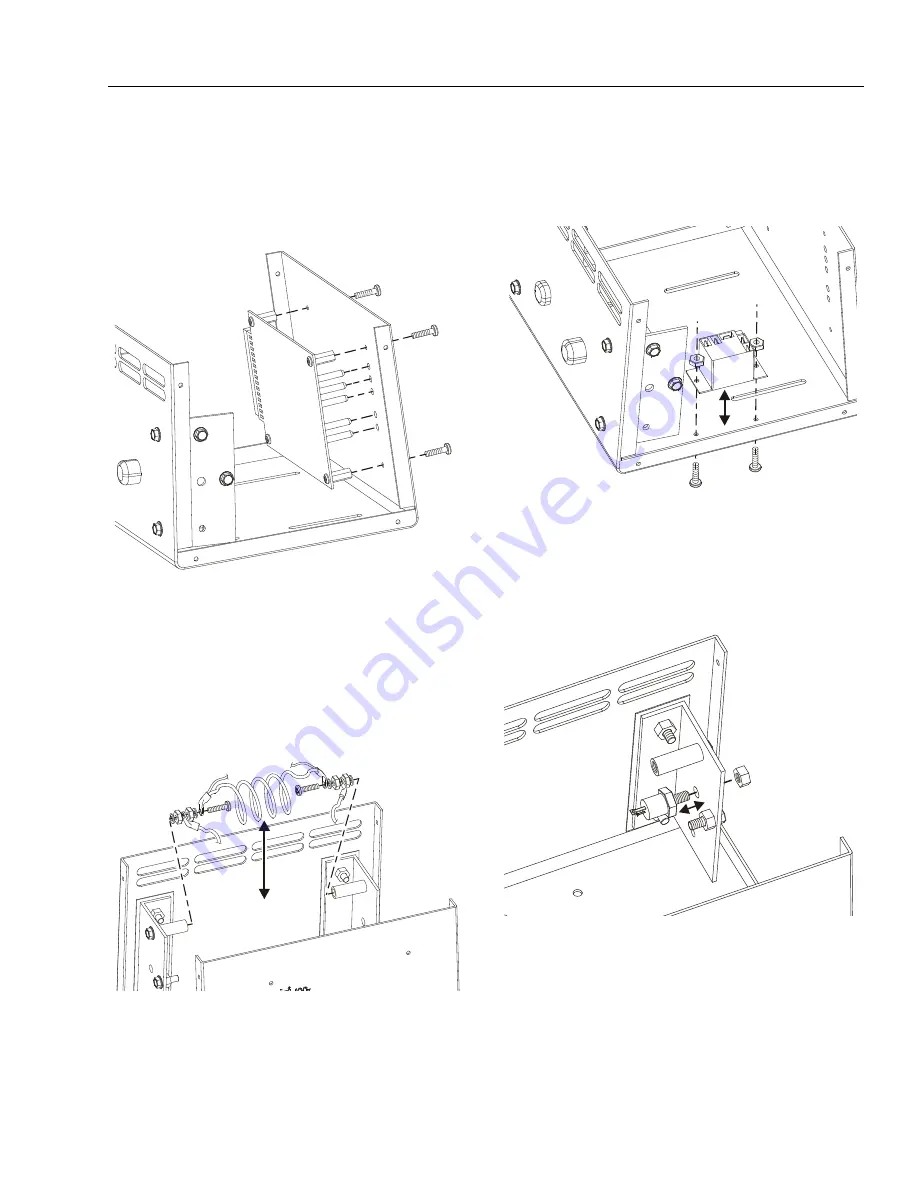
Printed Circuit Board Replacement
1.
Disconnect the wide wiring connector from the end of
the circuit board.
2.
Remove the four (4) screw attaching the card to the
front face of the charger chassis.
3.
Remove the circuit board.
Shunt Assembly Replacement
1.
Carefully remove the screw from each end of the shunt
assembly. The white insulator may need to be restrained
to keep it from turning while removing the shunt assem-
bly fasteners. Also make note of the position of each
washer, nut and wire connector when removing for later
assembly.
Interlock Relay Replacement
1.
Disconnect the wiring connected to the relay.
2.
Remove the two (2) nuts securing the interlock relay to
the chassis base.
3.
Remove the relay.
SCR Rectifier Replacement (Either Side)
1.
Remove the wiring from the SCR Rectifier.
2.
Remove the nut securing the rectifier to the insulated
aluminum chassis bracket.
3.
Remove the SCR Rectifier.
Summary of Contents for T500J
Page 1: ...Service and Maintenance Manual Model T500J PN 3121200 July 25 2018 Rev I AS NZS...
Page 2: ......
Page 16: ...xii 3121200 LIST OF TABLES TABLE NO TITLE PAGE NO This page left blank intentionally...
Page 36: ...SECTION 2 GENERAL 2 8 3121200 NOTES...
Page 143: ...SECTION 3 CHASSIS TURNTABLE 3121200 3 107 Figure 3 45 Battery Charger Schematic...
Page 234: ...SECTION 5 BASIC HYDRAULIC INFORMATION SCHEMATICS 5 60 3121200 NOTES...
Page 246: ...SECTION 6 JLG CONTROL SYSTEM 6 12 3121200 Figure 6 5 System Test Flow Chart Platform Tests...
Page 304: ...SECTION 7 BASIC ELECTRICAL INFORMATION SCHEMATICS 7 32 3121200 NOTES...
Page 305: ......


