SECTION 4 - BOOM & PLATFORM
4-22
3121200
4.
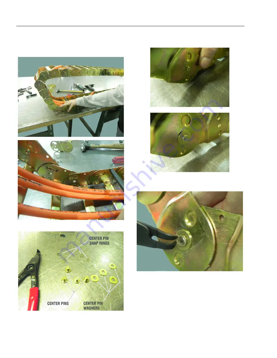
Pull moving end over track so new connection is posi-
tioned in curve of powertrack. Round half-shears will
rotate into cut-outs.
5.
Parts shown below connect new link to powertrack.
6.
Push pin through center hole. Slide washer on pin.
7.
Install snap ring in groove on pin. Repeat pin installation
steps for all center holes with rivets removed.
Summary of Contents for T500J
Page 1: ...Service and Maintenance Manual Model T500J PN 3121200 July 25 2018 Rev I AS NZS...
Page 2: ......
Page 16: ...xii 3121200 LIST OF TABLES TABLE NO TITLE PAGE NO This page left blank intentionally...
Page 36: ...SECTION 2 GENERAL 2 8 3121200 NOTES...
Page 143: ...SECTION 3 CHASSIS TURNTABLE 3121200 3 107 Figure 3 45 Battery Charger Schematic...
Page 234: ...SECTION 5 BASIC HYDRAULIC INFORMATION SCHEMATICS 5 60 3121200 NOTES...
Page 246: ...SECTION 6 JLG CONTROL SYSTEM 6 12 3121200 Figure 6 5 System Test Flow Chart Platform Tests...
Page 304: ...SECTION 7 BASIC ELECTRICAL INFORMATION SCHEMATICS 7 32 3121200 NOTES...
Page 305: ......


