SECTION 3 - CHASSIS & TURNTABLE
3121200
3-5
3.5
MECHANICAL BRAKE
Brake Maintenance
WHEEL BRAKES
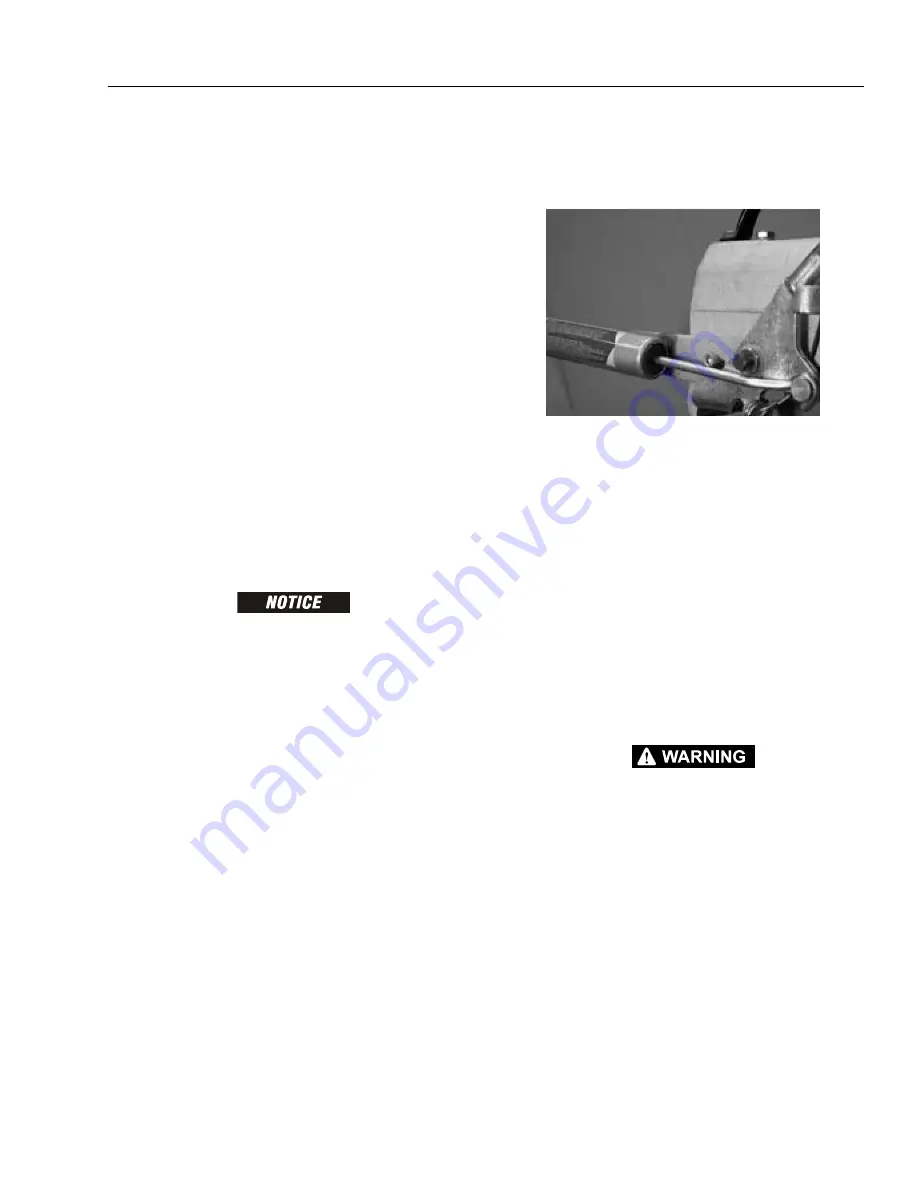
The linings of the wheel brakes are wearing parts, so their con-
dition must be checked every 3000 miles (5000 km) or every
year, whichever comes first, using the view holes on the wheel
backing plates.
If the connecting rod can be pushed in more than approxi-
mately 45 mm when the over-run braking system is checked
as outlined above, this is a sure sign of advanced wearing of
the brake linings. If this is the case, the wheel brakes must be
readjusted at a qualified workshop, and if necessary, the brake
shoes must be replaced.
WHEEL MOUNTS
The wheel hubs have maintenance-free, double row angular
ball bearings.
The sideways bearing play should be checked at intervals of
3000 miles (5000 km) by checking whether the wheels have
sideways play when the trailer is jacked up. If there is detect-
able play, the trailer should be checked at a qualified work-
shop.
REPLACING BRAKE ASSEMBLY COMPLETE
IT IS RECOMMENDED THAT THE BRAKE ASSEMBLIES ARE REPLACED IN AXLE
SETS.
1.
Follow steps 1 thru 7 of REPLACING BRAKE SHOES.
2.
The brake assemblies are left and right specific, check
the new assembly against the one fitted noting the posi-
tion of the brake cable attachment. Remove the four
bolts securing the backplate to the axle, remove the old
assembly and install the new using the proper torque
values.
3.
Continue with the procedure under REPLACING BRAKE
SHOES, starting at step 18.
4.
Follow the procedure under ADJUSTMENT.
REPLACING BRAKE SHOES
Place the trailer on stands with all wheels off of the ground.
WARNING: The handbrake should be released and the hand-
brake locking bolt installed.
Some couplings do not have provision for the locking bolt. In
this case or if a bolt cannot be used the handbrake lever
should be secured in the off position to prevent the handbrake
lever from operating.
NOTE:
It is recommended that the brake shoes are replaced in axle
sets.
1.
Remove the wheels.
2.
Remove the hub cap.
3.
Slacken off the brake adjuster bolt until free. Some brake
assemblies have a ratchet accessible through an open-
ing in the backplate instead of the bolt.
4.
Remove the axle nut, this may be a castellated nut
retained with a cotter pin or it may be a locknut.
5.
Remove the brake drum (hub puller may be required)
taking care not to displace the bearings.
AVOID INHALING BRAKE DUST. DON’T USE AN AIR LINE TO CLEAN THE DRUM.
CAREFULLY REMOVE THE DUST USING A SMALL BRUSH.
6.
Check the condition of the brake drum. Replace the
brake drum if deep score marks are visible.
Summary of Contents for T500J
Page 1: ...Service and Maintenance Manual Model T500J PN 3121200 July 25 2018 Rev I AS NZS...
Page 2: ......
Page 16: ...xii 3121200 LIST OF TABLES TABLE NO TITLE PAGE NO This page left blank intentionally...
Page 36: ...SECTION 2 GENERAL 2 8 3121200 NOTES...
Page 143: ...SECTION 3 CHASSIS TURNTABLE 3121200 3 107 Figure 3 45 Battery Charger Schematic...
Page 234: ...SECTION 5 BASIC HYDRAULIC INFORMATION SCHEMATICS 5 60 3121200 NOTES...
Page 246: ...SECTION 6 JLG CONTROL SYSTEM 6 12 3121200 Figure 6 5 System Test Flow Chart Platform Tests...
Page 304: ...SECTION 7 BASIC ELECTRICAL INFORMATION SCHEMATICS 7 32 3121200 NOTES...
Page 305: ......


