SECTION 3 - CHASSIS & TURNTABLE
3-16
3121200
2.
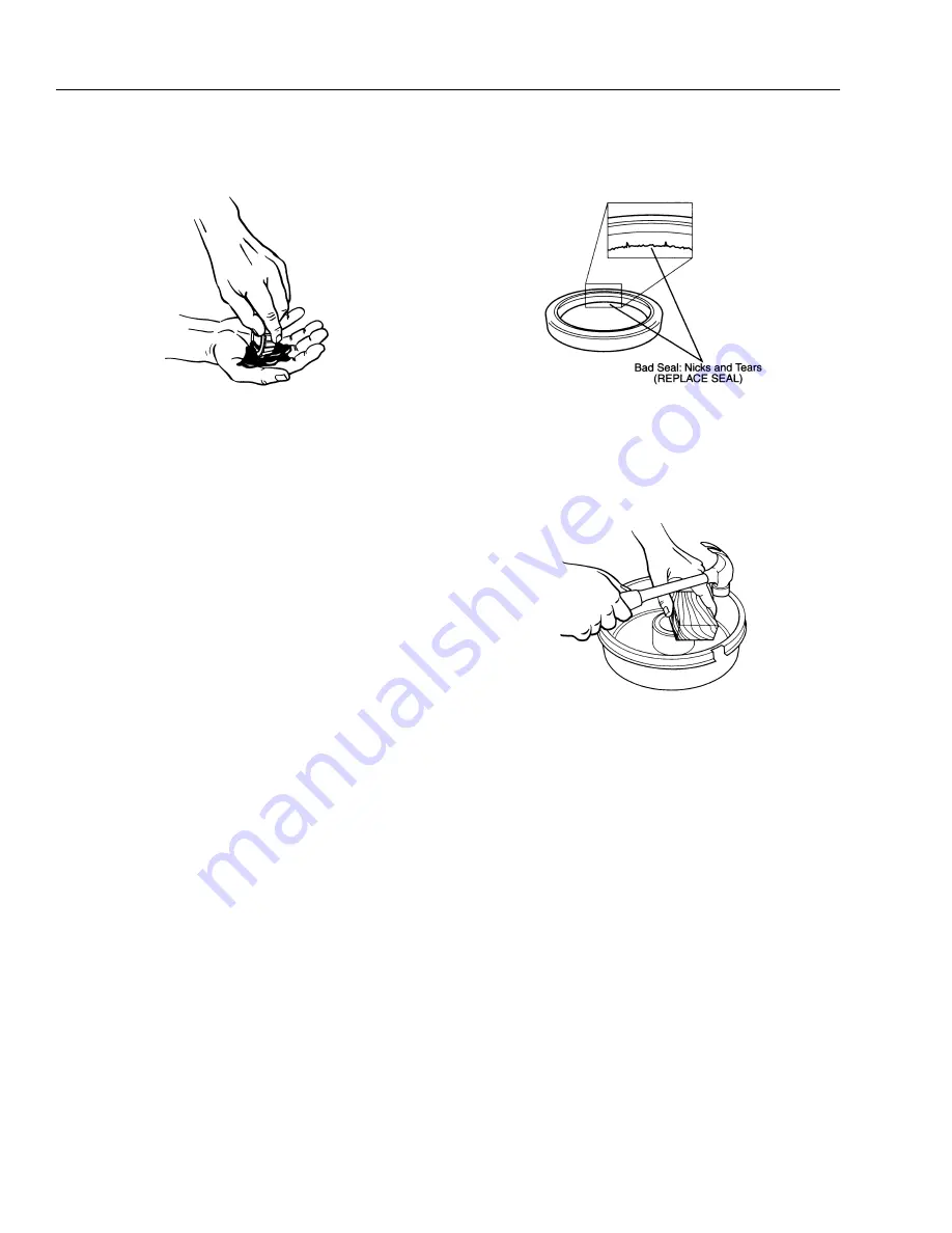
Press a section of the widest end of the bearing into the
outer edge of the grease pile closest to the thumb forc-
ing grease into the interior of the bearing.
3.
Repeat this while rotating the bearing from roller to
roller.
4.
Continue this process until the entire bearing is com-
pletely filled with grease.
5.
Before installing, apply a light coat of grease on the
bearing cup.
Thickener Type..................................................... Lithium Complex
Dropping Point ...................................... 419° F (215°C) Minimum
Consistency .........................................................................NLGI No. 2
Additives ............................EP, Corrosion & Oxidation Inhibitors
Viscosity Index............................................................... 80 Minimum
Approved Sources:
Mobil Oil ....................................... Mobilgrease HP, Mobilith AW2
Exxon/Standard ..................................................................Ronex MP
Kendall Refining Co. ...................................................Kendall L-427
Ashland Oil Co. ................................. Valvoline Multipurpose GM
76 Lubricants ............................................................76 Multiplex EP
Citgo Petroleum...................................................... Lithoplex MP#2
Mystik .................................................. Mystik JT-6 Hi Temp Grease
Pennzoil ...........................Premium Wheel Bearing Grease 707L
Seal Inspection and Replacement
Whenever the hub is removed, inspect the seal to assure it is
not nicked or torn and is still capable of properly sealing the
bearing cavity. If there is any question of condition, replace the
seal.
To replace the seal:
1.
Pry the seal out of the hub with a screwdriver. Never
drive the seal out with the inner bearing as you may
damage the bearing.
2.
Apply a sealant, such as PERMATEX, to the outside of the
new seal.
NOTE:
Permatex sealant should not be used on rubber encased
seals.
3.
Tap the new seal into place using a clean wooden block.
Bearing Adjustment
If the hub has been removed or bearing adjustment is
required, the following adjustment procedure must be fol-
lowed:
1.
Rotate the hub assembly slowly while tightening the
spindle nut to approximately 50 ft.lbs. (68 Nm).
2.
Loosen the spindle nut to remove the torque. DO NOT
ROTATE THE HUB.
3.
Finger tighten the spindle nut until just snug.
4.
Back the spindle nut out slightly until the first castella-
tion lines up with the cotter key hole and insert the cot-
ter pin.
5.
Bend over the cotter pin legs to secure the nut.
NOTE:
The nut should be free to move with the only restraint
being the cotter pin.
Summary of Contents for T500J
Page 1: ...Service and Maintenance Manual Model T500J PN 3121200 July 25 2018 Rev I AS NZS...
Page 2: ......
Page 16: ...xii 3121200 LIST OF TABLES TABLE NO TITLE PAGE NO This page left blank intentionally...
Page 36: ...SECTION 2 GENERAL 2 8 3121200 NOTES...
Page 143: ...SECTION 3 CHASSIS TURNTABLE 3121200 3 107 Figure 3 45 Battery Charger Schematic...
Page 234: ...SECTION 5 BASIC HYDRAULIC INFORMATION SCHEMATICS 5 60 3121200 NOTES...
Page 246: ...SECTION 6 JLG CONTROL SYSTEM 6 12 3121200 Figure 6 5 System Test Flow Chart Platform Tests...
Page 304: ...SECTION 7 BASIC ELECTRICAL INFORMATION SCHEMATICS 7 32 3121200 NOTES...
Page 305: ......


