SECTION 3 - CHASSIS & TURNTABLE
3121200
3-33
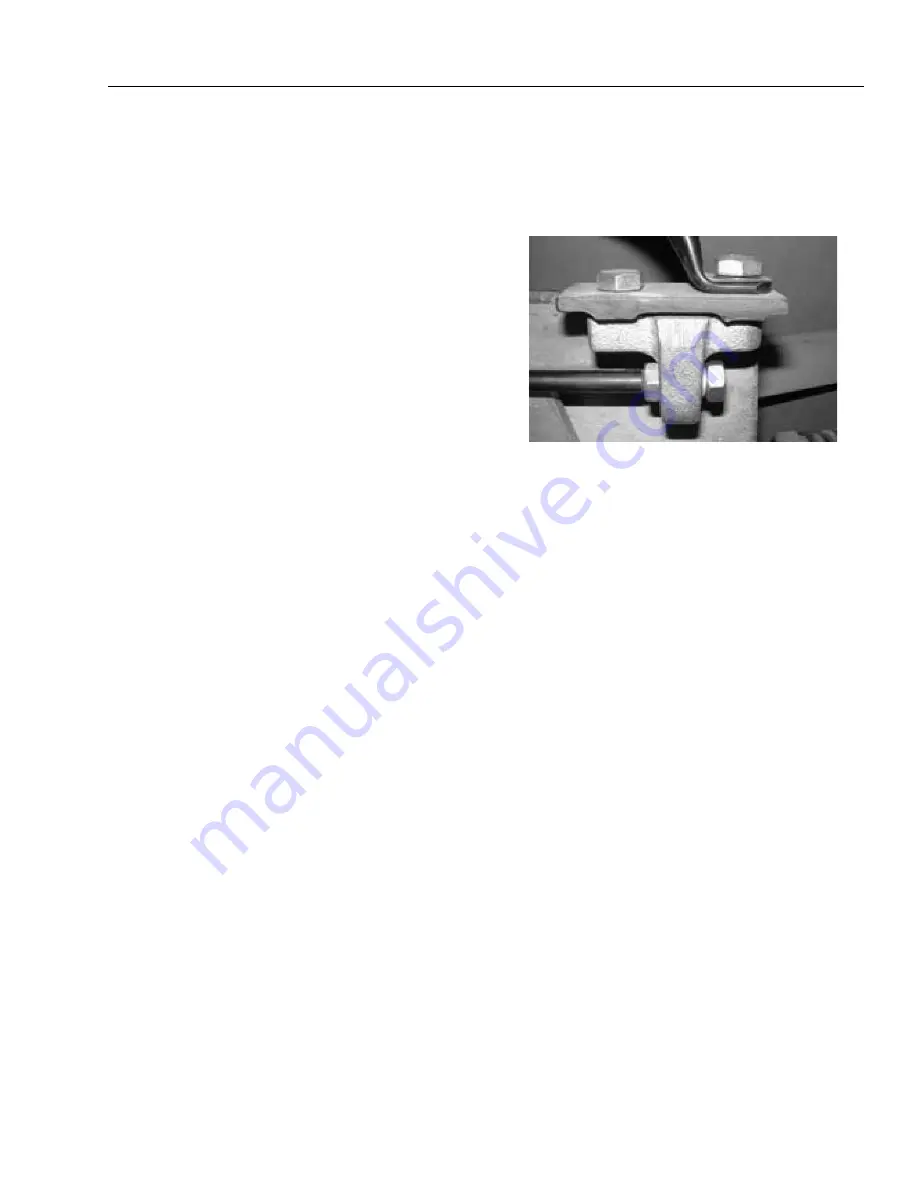
Coupling Head Maintenance
REPLACING
Prior to replacing the coupling head, it is essential to confirm
the condition of the damper. Test the Damper as outlined
under DAMPER REACTION TEST.
1.
Follow steps 1 thru 4 under Damper Maintenance -
REMOVAL.
2.
If you have been able to remove the coupling head/eye
as instructed under Damper Maintenance - REMOVAL
step 4, go to step 5 below, otherwise proceed with step
3.
3.
The damper will now be retained between the front
coupling/eye bolt and the rear damper bracket. It is now
necessary to remove the damper without destroying it.
WARNING: Proceed with caution!
The most efficient
method is to remove the rear damper mounting bracket,
but depending upon the coupling, there may still be
tension in the damper.
4.
Place a lever against the rear damper in such a manner
that once the mounting bracket bolts are removed the
tension can be released slowly. Take the tension and
remove the mounting bracket bolts, release the tension
in the damper.
5.
Inspect the shaft for damage, dress burrs, and clean any
dirt as the new coupling will be a close fit on the shaft.
6.
If a new bellows is to be fitted cut the tie-wrap and dis-
card the old one, fit the new and secure with a tie-strap.
7.
Trial fit the new coupling. It should slide into place with-
out any undue force. DO NOT hammer the coupling into
place, this can damage the coupling itself or the over-
run mechanism. If it proves to be tight, remove it and
thoroughly clean the shaft inspecting for burrs.
8.
Fit the bolts, washers and secure with NEW locking nuts
and torque to 214 ft. lbs. (290 Nm). DO NOT re-use the
old nuts as this is safety critical. Fit the plastic nut covers.
Where the damper has been removed ensure that the
coupling head rear bolt passes through the hole in the
damper body.
NOTE:
If there are any doubts about the condition of the damper,
install a new one.
9.
If the damper has been released the rear mounting
bracket will need to be re-fitted. This means that the
damper needs to be compressed so the bolts can be
installed.
WARNING: Proceed with caution!
Compress
the damper with the lever and secure the mounting
bracket bolts.
10.
Reinstall the bellows with the coupling/eye horizontal
taking care not to tear or damage the material.
If the replacement coupling/eye is a different part than
the original:
a.
Always ensure the corresponding length bolts are
used.
b.
Always ensure a compatible bellows is used.
c.
Always ensure the hole sizes in the coupling and
draw-bar tube match and the correct size bolts are
used.
DAMPER REACTION TEST
1.
Pull the handbrake lever on as far as possible.
2.
Push the ball coupling as far back into the overrunning
hitch as it will go. This requires force to compress and
should extend smoothly when released.
3.
If the draw tube is impossible to compress, compresses
with just spring force and no damping resistance, or the
extension is very rapid, the damper must be replaced by
carefully following the replacement instructions above.
Summary of Contents for T500J
Page 1: ...Service and Maintenance Manual Model T500J PN 3121200 July 25 2018 Rev I AS NZS...
Page 2: ......
Page 16: ...xii 3121200 LIST OF TABLES TABLE NO TITLE PAGE NO This page left blank intentionally...
Page 36: ...SECTION 2 GENERAL 2 8 3121200 NOTES...
Page 143: ...SECTION 3 CHASSIS TURNTABLE 3121200 3 107 Figure 3 45 Battery Charger Schematic...
Page 234: ...SECTION 5 BASIC HYDRAULIC INFORMATION SCHEMATICS 5 60 3121200 NOTES...
Page 246: ...SECTION 6 JLG CONTROL SYSTEM 6 12 3121200 Figure 6 5 System Test Flow Chart Platform Tests...
Page 304: ...SECTION 7 BASIC ELECTRICAL INFORMATION SCHEMATICS 7 32 3121200 NOTES...
Page 305: ......


