SECTION 3 - CHASSIS & TURNTABLE
3-34
3121200
Damper Maintenance
The dampers assembled within the overrun coupling is pres-
surized. During assembly, the damper is reloaded and com-
pressed in order that the coupling operates correctly. Care
must be exercised when working on, handling, and disposing
of the coupling/damper. This is especially important if any
damage or misuse of the coupling has occurred.
REMOVAL
DO NOT POSITION ANYTHING OR STAND IMMEDIATELY TO THE FRONT OR
REAR OF THE COUPLING ASSEMBLY IN CASE A DAMPER FAILS DURING THE
PROCESS.
1.
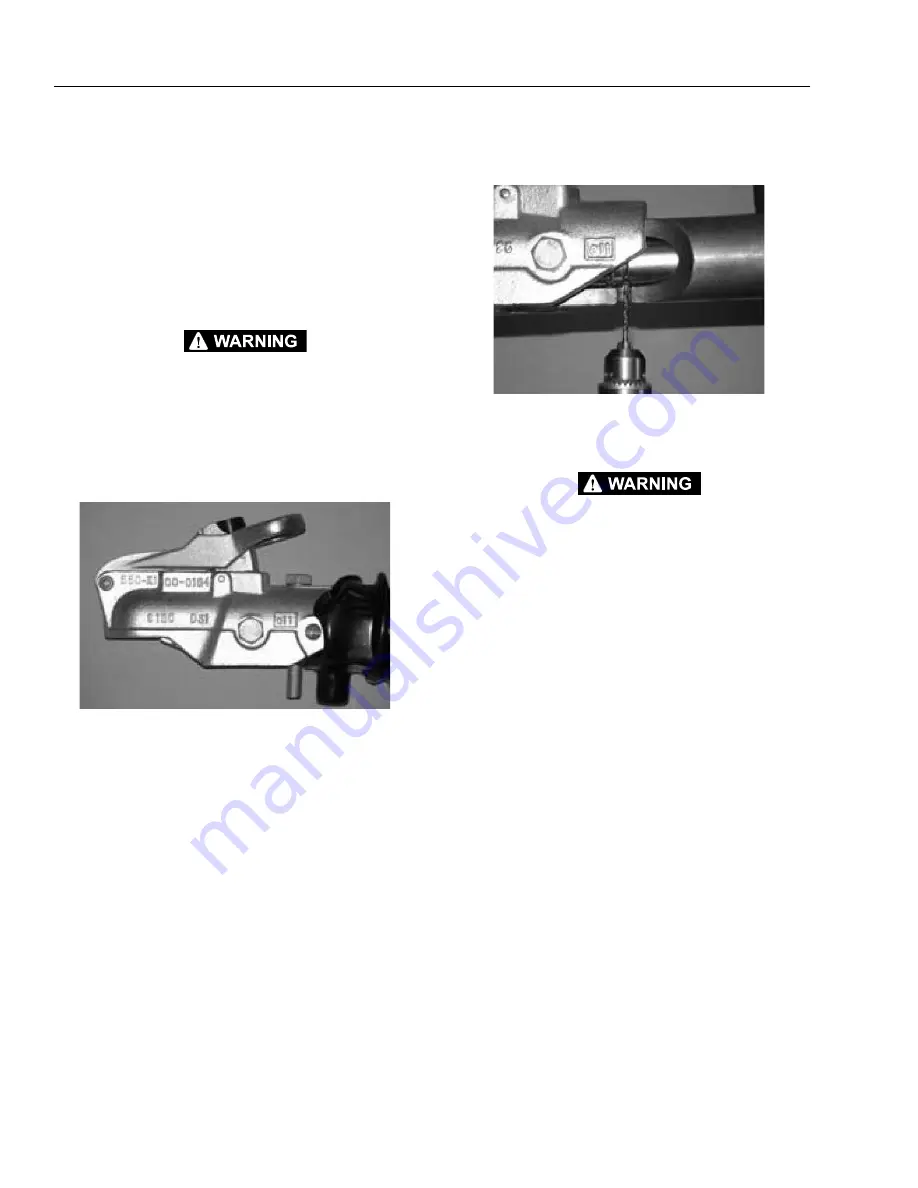
Pull back the bellows from the coupling to expose the
two retaining bolts.
2.
Undo the self locking nut from the rear bolt of the cou-
pling as shown.
3.
Remove the rear bolt; force may be required as the
damper may still be preloaded. Raise the coupling oper-
ating handle in order to fully remove the bolt if neces-
sary.
4.
When the rear bolt is removed the damper will move
forward to rest upon the front bolt.
In some instances a retaining pin is used; located
between the bolt holes. This pin will hold the damper in
its original position and will therefore need to be
removed in the following manner.
a.
Undo the self locking nut from the front bolt, extract
the bolt and remove the head.
b.
Replace both bolts in the draw tube and finger
tighten the bolts.
c.
Knock out the retaining pin and remove the rear
bolt, this will allow the damper to move forward and
contact the front bolt.
5.
From underneath, through the bolt hole in the draw
tube, drill a 3 mm hole into the damper body to a depth
of 8 mm.
OBSERVE NORMAL SAFETY PROCEDURES FOR THE USE OF HAND TOOLS.
WEAR SAFETY GLASSES.
DO NOT LIE IMMEDIATELY UNDERNEATH THE BOLT HOLE WHEN DRILLING.
WHEN THE DRILL PENETRATES THE DAMPER BODY GAS WILL BE ALLOWED TO
ESCAPE.
6.
The pressure in the damper should now have been dis-
charged. Remove the self locking nut on the front bolt of
the coupling head. Remove the bolt and the coupling
head. If the bolt is difficult to remove, it indicates that
there is still residual force in the damper and step 5
should be repeated.
7.
Remove the rear damper bracket retaining bolts. Also
remove the nuts and spring washer from the rear of the
damper.
8.
The de-pressurized damper can now be removed by
sliding the damper forward through the draw tube and
be disposed of.
Summary of Contents for T500J
Page 1: ...Service and Maintenance Manual Model T500J PN 3121200 July 25 2018 Rev I AS NZS...
Page 2: ......
Page 16: ...xii 3121200 LIST OF TABLES TABLE NO TITLE PAGE NO This page left blank intentionally...
Page 36: ...SECTION 2 GENERAL 2 8 3121200 NOTES...
Page 143: ...SECTION 3 CHASSIS TURNTABLE 3121200 3 107 Figure 3 45 Battery Charger Schematic...
Page 234: ...SECTION 5 BASIC HYDRAULIC INFORMATION SCHEMATICS 5 60 3121200 NOTES...
Page 246: ...SECTION 6 JLG CONTROL SYSTEM 6 12 3121200 Figure 6 5 System Test Flow Chart Platform Tests...
Page 304: ...SECTION 7 BASIC ELECTRICAL INFORMATION SCHEMATICS 7 32 3121200 NOTES...
Page 305: ......


