


english
15
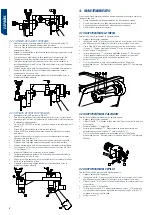
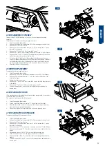
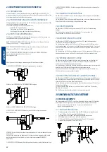
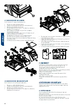
3.1.2 cutting dePth adJustMent
•
lock the rotation of the clamp on the right side, operating the handle “16”.
•
Fasten the adjustment rods in the clamp.
•
unlock the rotation of the handle “12”, loosening the screw “M”.
•
activate the probe spring, acting on handle “15”.
•
Move the carriage forward, so that the adjustment rods rest on the “t” probe
and the “c” cutter.
•
operating the handle “12”, move the probe forward or backward, until the
probe “t” is resting on the adjusting rod “Vt”, the “c” cutter lightly rubs the
adjustment rod “Vc”.
•
re-tighten the “M” screw.
16
12
M
15
T
C
VT
VC
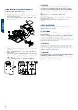
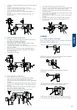
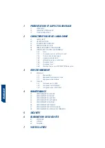
3.1.3 lateral stoP adJustMent
•
the bit carriage is supplied with the factory-set lateral stops, so it is not
necessary to adjust them again.
•
however, after replacing the lateral stops, the way to set them would be as
follows:
•
support the right side of the lateral stop “n1”, against the internal bushing
“c1”
•
in this position, tighten the “r” screw to fix the lateral stop “n1”.
•
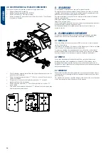
attach a “long male” type key to the right-side clamp, so that the bit is butted
against the lateral stop “n1”.
•
lock the “X” axis of the carriage, operating the handle “14”.
•
execute a straight groove of approximately 8 mm. of depth.
N1
R
C1
•
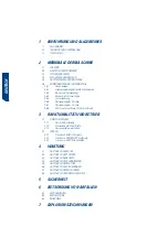
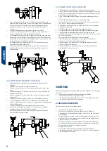
loosen the screw “Q” that fixes the internal bushing “c2”.
•
release the key on the right-hand side clamp and attach it to the left side clamp,
so that the “t” probe is inserted into the slot that we have made in the key.
•
in this key position, support the left side of the lateral stop “n2”, against the bit
of the key.
•
in this position of the lateral stop “n2”, tighten the screw “r” to fix the lateral stop
“n2”.
•
Move the inner bushing “c2”, until it touches the right-side of the lateral stop “n2”.
•
in this position of the internal bushing “c2”, lock it by means of the “Q” screw.
•
now you can unlock the X axis of the carriage, operating the handle “14”
N2
C2
Q
T
R
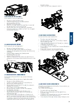
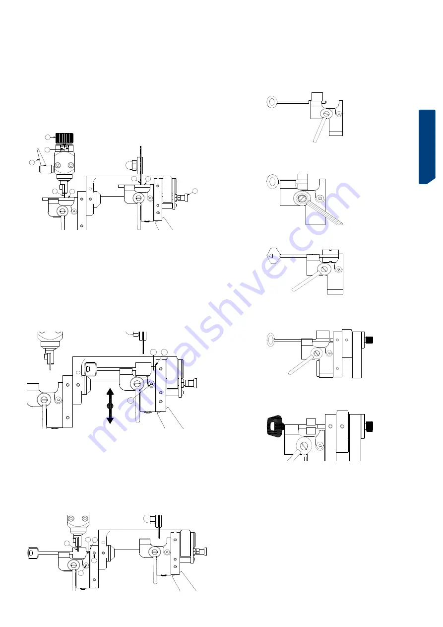
3.2 ENCRYPTION
3.2.1 encrYPtion oF the Mortise KeYs
Fasten the key in the clamp. depending on the type of key we want to cut, the stop of
the key will be made in one of the following ways:
- Key with stop on the stem:
stop against the left side of the clamp.
- SHORT key (male/female) (simple/double probe):
stop of the right side of the bit against the side left of the cutter and the Probe.
- LONG MALE key (simple/double probe):
stop against the lateral stop.
- LONG fEMALE key (simple/double probe):
stop against the lateral stop. use counterpoints for female key.
-SPECIAL MALE key: with plastic head, with square stem, ......:
cutter-Probe stop. use counterpoints for male key.
•
For greater comfort when fastening the keys in the clamps, it is recommended
to lock the X axis and the Y axis (in this way, the machine carriage stays still).
it is also recommended to lock the rotation of the right clamp, to facilitate the
orientation of the key bit.
•
start the rotation of the cutter, activating the corresponding switch.
•
carefully bring the keys towards the cutter and the Probe. we recommend
working slowly, without forcing the cutter.
•
the round point is achieved by turning the lever “6” (moving the lever from top
to bottom). this rotation is internally limited. in the case of deep teeth located
on the right end of the bit, limit the rotation of the lever so that the bit does not
touch the lateral stop.
•
For double-bit keys, turn both keys 180º and repeat the operations already
described.
•
if during cutting, burrs are produced in the cut key, these will be eliminated
using the brush that has been provided with the machine for this purpose.
Summary of Contents for VOLGA BIT
Page 2: ......
Page 3: ...Espa ol VOLGA BIT MANUAL DE INSTRUCCIONES M QUINA DUPLICADORA...
Page 11: ...english VOLGA BIT USER manual KEY CUTTING MACHINE...
Page 19: ...deutsch VOLGA BIT Anweisungshandbuch KOPIERMASCHINE...
Page 28: ...deutsch 28...
Page 29: ...francaise VOLGA BIT MANUEL D INSTRUCTIONS MACHINE A REPRODUIRE...
Page 38: ...francaise 38...
Page 39: ...portuguese VOLGA BIT Manual de instru es M QUINA DUPLICADORA...
Page 47: ...portuguese 47...
Page 48: ...portuguese 48...
Page 49: ...POLISH VOLGA BIT PODR CZNIK U YTKOWNIKA maszyna do kopiowania...


