NT-2000 REF Manual
User-Level Troubleshooting
5-5
5 . 4 . P o o r
R e c ep t i o n
The following description of the symptoms assumes that NAVTEX messages were
properly received for some time after initial installation time, and all message types and
transmitter IDs you wish to receive are selected (via the steps given in paragraph 4.8).
Symptom
Suggested Solution
Messages can be received in the
daytime, but with many error
characters (
*
) at all times.
NAVTEX messages can be received but
with many error characters (asterisks)
and often cannot be stored.
1. Check if you are located within the service
area covered by the ground wave of the
desired station. The area is normally 200
to 400 nautical miles from each station
during daytime hours. At night, NAVTEX
signals can travel distances in excess of
1000 nautical miles depending on the
season and ionospheric conditions.
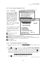
2. Run the self–diagnostic tests as per
paragraph 4.12, and check the receiver
test results. If the result for the receiver
in question is “
FAILED
,” ask your
dealer/qualified service engineer to check
the related wiring harnesses to/from the
receiver PCB or replace the PCB.
3. Check if you have recently installed an
electronic device near the receiver cabinet
receiver or near the antenna. Turn off or
relocate such equipment away from the
NAVTEX receiver, and see if any
improvement can be obtained.
4. Unplug the antenna cable from the BNC
connector on the rear apron, and check
the voltage at the center conductor. It
should be 8V+ on the
ACTIVE ANT
and
518
kHz
connectors, and 12V+ on the
490 / 4209.5 kHz
connector. If no voltage
is present or the voltage is extremely low,
ask your dealer/qualified service engineer
to check the related connections to/from
the power supply PCB first and to
replace the PCB, if necessary.
5. Suspect that the preamplifier in the active
antenna unit is failing or water intruded
into the cable via the junction. Check by
replacing the amplifier unit and/or the
cable.
If a correct replacement antenna is not
available, run approx. 5 meters of
insulated wire from the center conductor
of the appropriate connector as a
temporary long wire antenna, and place it
as high as possible from the ground level.
< WARNING>
DO NOT SHORT THE OTHER END OF
THE WIRE ANTENNA TO GROUND, OR
DAMAGE TO THE UNIT’S POWER
SUPPLY
WILL RESULT
.


