Hardware Used
AA
BB
1
x 4
x 4
M
AA
BB
Bolt M6x10
M6 nut
14
13
Assembly Procedure
2
Hardware Used
CC
x 8
screw M5x10
HH
x 8
Screw 3/16”
3
HH
CC
D
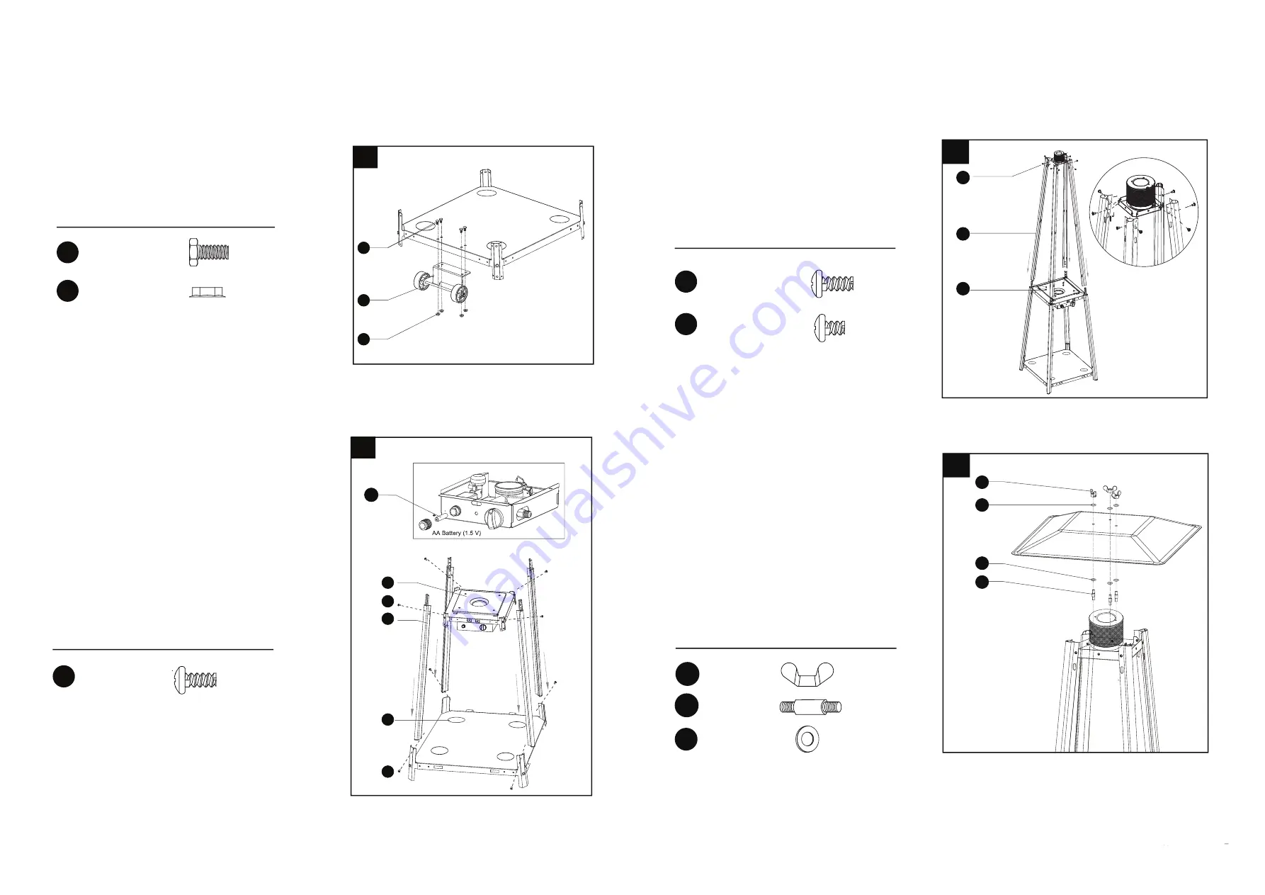
1.Assemble the wheel assembly (M) to the
bottom plate (N) using 4pcs bolt M6x10
(AA) and 4pcs M6 nut (BB).
Hardware Used
CC
x 8
screw M5x10
2-1. Unscrew the ignition, load small battery,
tighten the ignition.
2-2. Insert the pins of the bottom plate (N) to the
holes of lower support (L), press to secure the
pins. using 4pcs screw M5x10 to secure the
bottom plate and lower support.
Insert the pins of the control box assy (K) to the
holes of lower support (L), press to secure the
pins. using 4pcs screw M5x10 to secure the lower
support and control box assy.
3. Insert upper support (D) to lower support
(L) using 8pcs screw M5x10.
Assemble top plate assy (B) to upper
support (D) using 8pcs screw 3/16”.
L
K
CC
CC
N
Hardware Used
4
4
.
Assemble the reflector (A) onto the top
plate assy (B).
Screw the 3pcs stud (DD) on the top plate
assy (B), put 3pcs flat washer (FF) onto the
top of stud (DD), then put the reflector on
the the stud (DD), secure them with 3pcs
flat washer (FF) and 3pcs wing nut (EE).
EE
FF
FF
DD
x 3
x 3
x 6
EE
Wing nut
Stud
DD
FF
Flat washer
ATTENTION:
Ensure control box and front panel are on
opposite side to wheels.
NN
Summary of Contents for JMC-OSPH-SS
Page 1: ......


