background image

16

15


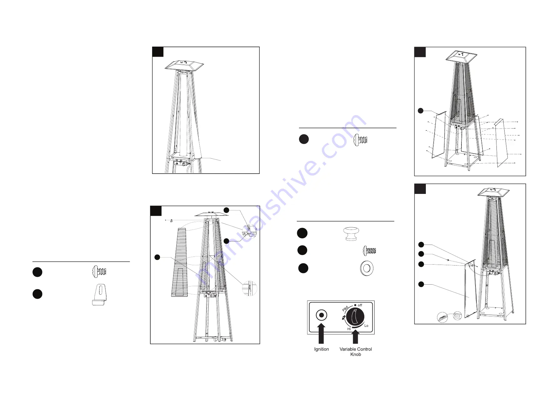
6.Assembly the protective guard (E).
Hang the hooks of the protective guard
(E) onto the holes in supports
Secure the protective guards (E) with fixing
brackets (GG) with 4pcs screw Screw 3/16” 
 (HH).

Hardware Used

6

E

HH

GG

GG

Fixing 
Bracket

x 4

7

8

HH

Hardware Used

HH

x 18

Screw 3/16” 

II

JJ

KK

H

8

.

Install the knob (II) to screw M4x8 (KK)
and large flat washer (JJ).
Put the pothook of front panel (H) to the
holes of bottom plate (N).

Hardware Used

x 1

I I

Knob

KK

x 1

x 1

Screw M4 X 8

HH

x 4

Screw 3/16” 

JJ

Large flat washer

7. Assemble three side panels (G) to heater 
using 18pcs screw 3/16”.


Attention:

Do not cover the front side where the control 
knob is.

5

5. Carefully install the glass tube (C) by
lifting up and inserting through the center
hole in the top plate assy (B). Ensure the 
black silicone ring (F) is attached to the 
lower edge of the glass tube (C) as illustrated.
Slide the glass tube (C) through the hole
of the lower plate cover and onto the middle
plate (J). Check and ensure that the glass
tube (C) is positioned properly and is
completely covering the center hole of
the middle plate(J).

To aid in installation
place black silicone
ring on the middle
plate and then
install glass tube.
Ensure the rim of
the glass tube sits
firmly in the black
silicone ring.

WARNING! The black
silicone ring must be in place
prior to operating the heater.

BLACK SILICONE
RING


ATTENTION: 

Please unscrew Igniton to put in battery.

Summary of Contents for JMC-OSPH-SS

Page 1: ......

Page 2: ...surface area is the sum of the walls surface Improper installation adjustment alteration service or maintenance can cause injury or property damage Read the installation operating and maintenance ins...

Page 3: ...another leak test If bubbles continue appearing should be returned to hose s place of purchase If leak is at Regulator Cylinder Valve connection disconnect reconnect and perform another leak check If...

Page 4: ...and and allow the regulator to be connected easily After connecting the regulator tighten the hose clip with a screwdriver This product contains small batteries Swallowed small batteries can cause CHO...

Page 5: ...1 Ensure the variable control knob is at the OFF position 2 Connect the gas regulator to a compatible gas cylinder 3 Push and turn the variable control knob to the Pilot position and hold for 60 secon...

Page 6: ...e Butane propane or their mixtures Butane propane or their mixtures Butane propane or their mixtures GAS PRESSURE 28 30mbar 37 mbar 30 mbar 50mbar 37mbar OUTLET PRESSURE OF REGULATOR 30mbar 37 mbar 30...

Page 7: ...t L Control Box Assy K Middle Plate J Gas Hose Regulator I Wheel Assembly Bottom Plate M N Reflector Top Plate Assy Glass Tube Upper Support Protective Guard Black Silicone Ring Side Panel Front Panel...

Page 8: ...the pins of the control box assy K to the holes of lower support L press to secure the pins using 4pcs screw M5x10 to secure the lower support and control box assy 3 Insert upper support D to lower s...

Page 9: ...the front side where the control knob is 5 5 Carefully install the glass tube C by lifting up and inserting through the center hole in the top plate assy B Ensure the black silicone ring F is attache...

Page 10: ...Tighten connections Thermocouple faulty Replace thermocouple Anti tilt switch loose faulty Reconnect replace anti tilt switch Gas leak in line Check connections Lack of fuel pressure Tank near empty...

Reviews: