8
Packing List
Refer to this list as you unpack your NGT-12.5. We recommend that you check off each item as you unpack and
ensure that nothing is missing before you begin to assemble your telescope.
If any items appear to be missing, please contact your retailer or Jim's Mobile Incorporated (JMI). The original
packaging material may be required to file any claims with the shipper so please do not discard it.
Standard Equipment
Nose assembly
Diagonal mirror and holder
2-inch NGF-DX2 focuser (see options)
2-inch extension tube
2-inch to 1.25-inch adapter
26mm 1.25-inch Plössl eyepiece
8x50 finder scope and mounting bracket
Piggy-back camera mount and off-axis counterweight
Three (3) vinyl nose assembly foot covers
Six (6) Serrurier truss rods
Four (4) truss rod thumbscrews (one spare)
Three (3) truss rod sliding counterweights
Tub/ring assembly
Primary mirror (unless ordered without)
Primary mirror dust cover
3-point flotation mirror cell
Three (3) tub/mirror counterweights
Base/rocker assembly
Right ascension motor
Declination motor
Two (2) optical shaft encoders (4000 tic/rev)
Dual-axis drive corrector with 12vDC and 110vAC
adapters and Hand Unit
NGC-miniMAX computer with manual (see options)
Computer mounting bracket
Encoder cable
Three (3) leveling screw pads (metal discs)
Optional Equipment
Nose assembly light baffle
Focuser upgrade
NGF-DX2M
NGF-DX1
NGF-DX1M
DRO or DFC option
Telrad
adapter plate
Additional truss rod sliding counterweights
Truss rod light shroud
4" aperture stop added to mirror dust cover
Center counterweight for CCD Camera or other
heavy equipment
EZAlign polar alignment scope
NGC-MAX computer upgrade
SGT-MAX
Serial cable
Bbox serial interface (unless telescope was
ordered with NGC-MAX)
TheSky
software
12vDC 17 amp-hour portable battery pack
Handlebar and Wheels
Handlebar
Two (2) 6-inch ball-bearing solid rubber wheels
Observatory mounting hardware
Primary Mirror Installation
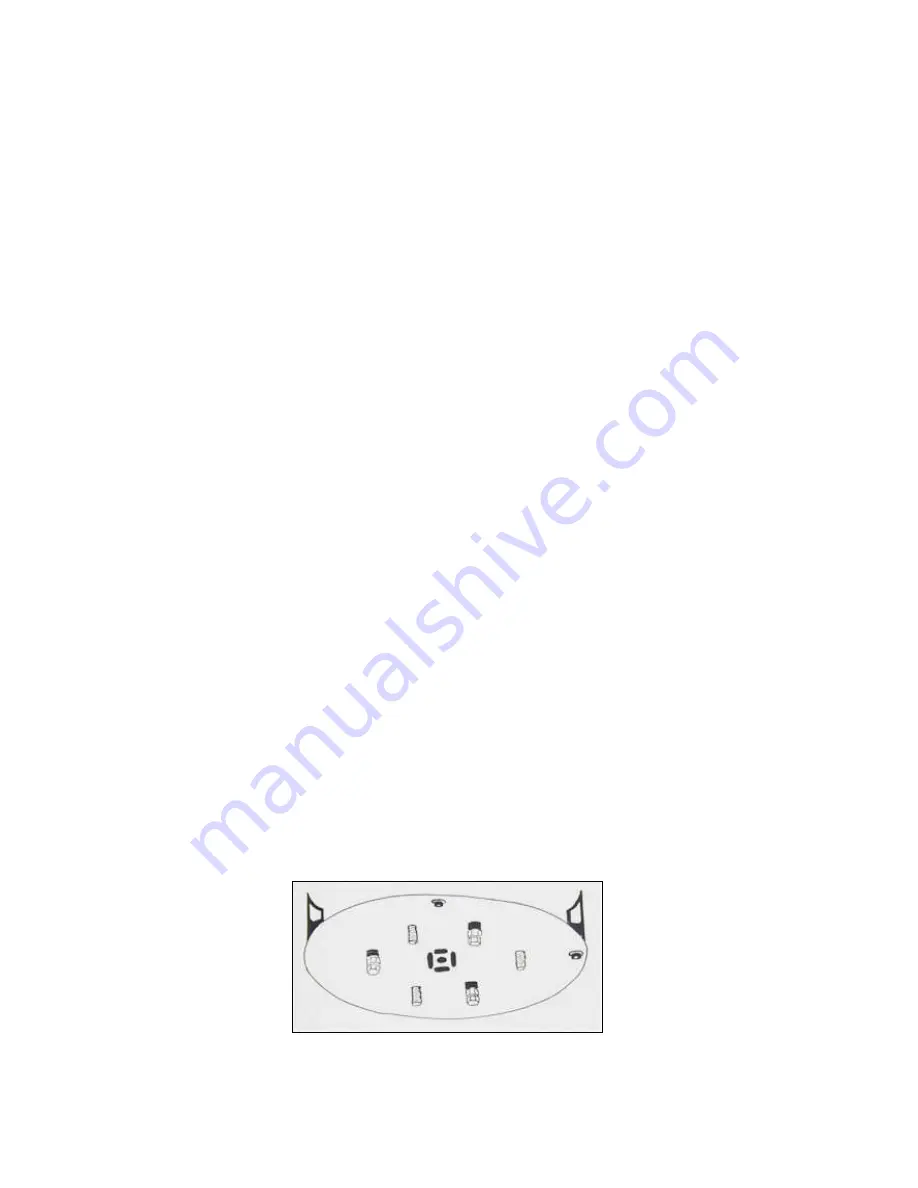
When installing the primary mirror, take care to align the studs on the underside of the mirror cell with the
corresponding holes in the bottom of the tub. See the mirror cell illustration for help in locating the studs.
If the mirror cell is installed without the alignment studs in proper orientation, the mirror will rest at an angle in the tub,
negating the collimation. When aligned properly, the studs are visible in their holes and can be felt underneath the
tub. When replacing the three mirror cell counterweights, take special care to tighten them equally. Unequal tension
will also affect positioning of the mirror cell and collimation.
Bottom view of mirror cell, showing alignment studs
Summary of Contents for NGT-12.5
Page 2: ......


