background image

9


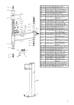
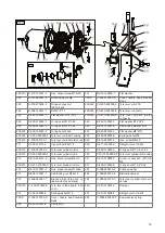
226

225

234

235

230

229

227

232

200-209

200-210

211

212

216

245

200-221

215

206

207

205

208

250

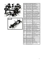
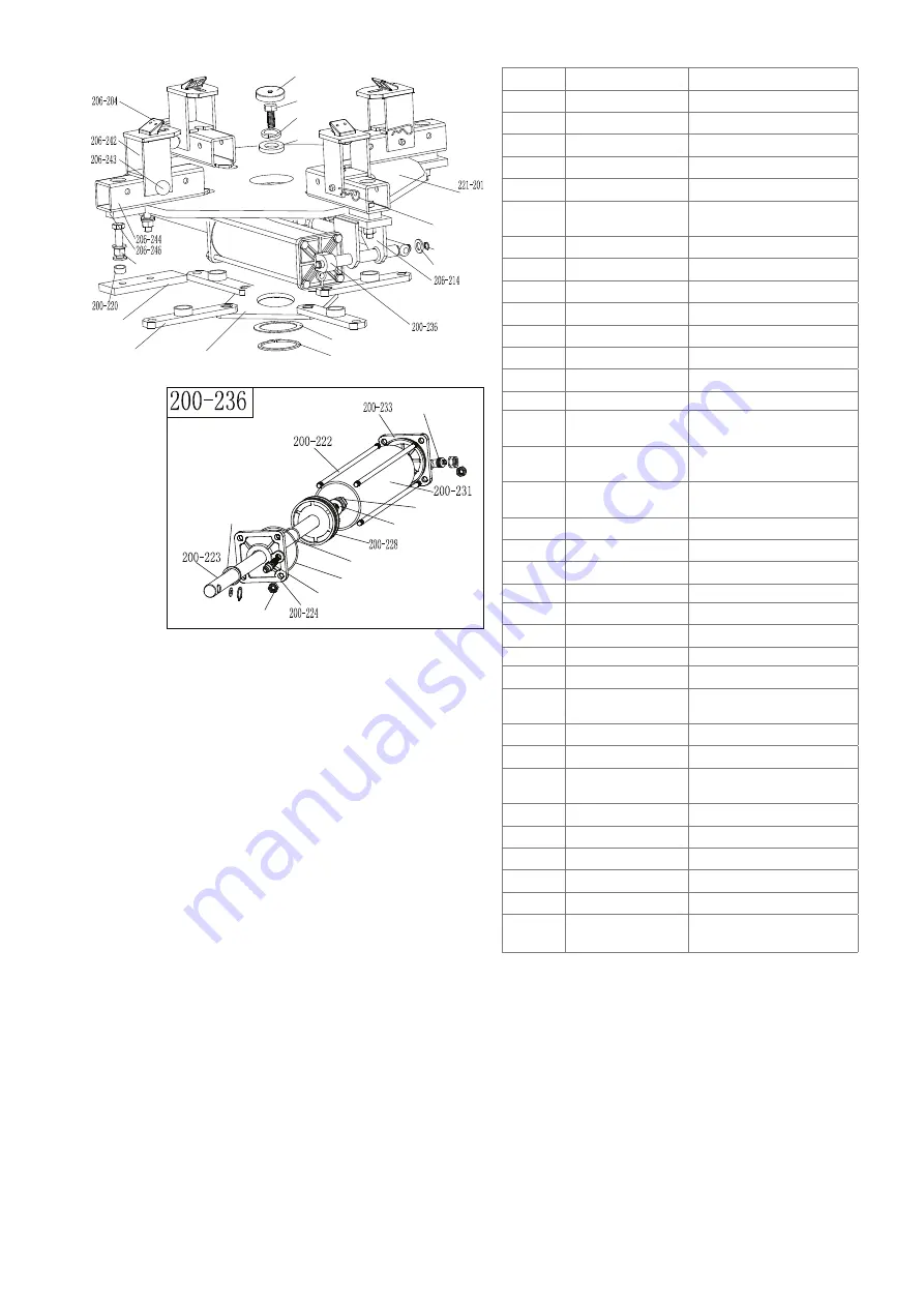
221-201 CX-221-130000-0 Turntable 630
206-204 C-206-570000-0

Clamping jaw 206

205

CX-200-140000-0 Large washer

206

B-050-160000-0

Spring washer Ø16

207

B-014-160401-0

Hex. screw M16x40

208

C-200-440000-0

Cover turntable

200-209 CX-200-310000-0 Structure connecting rod 

540

200-210 CX-200-280000-0 Square turntable 540
211

CX-200-290000-0 Washer square turntable

212

B-055-650001-0

Locking ring Ø65 (shaft)

206-214 CX-206-110100-0 Jaw slide with contact
215

B-040-122520-1

Flat washer Ø12x2

216

B-055-120001-0

Locking ring Ø12 (shaft)

200-220 CX-200-300000-0 Nut connecting rod
206-221 CX-206-110100-0 Clamping slide without pin
200-222 C-200-100400-0

Threaded connecting rod 

310

200-223 C-200-100200-0

Piston rod of clamping cy-

linder 320

224

C-200-100100-0

Clamping cylinder cover 

without handle

225

S-011-010808-0

Straight union 1/8“-Ø8

226

S-005-020075-0

V-seal 20*28*7.5

227

S-000-063265-0

O-ring seal 63*2.65

228

C-200-540000-0

Piston with seal ring

229

B-040-122520-1

Flat washer Ø 12x24x2

230

B-004-120071-1

Nut M12x7x1.75

200-231 C-200-100500-0

Clamping cylinder tube 279

232

S-000-019262-0

O-ring seal 19.6x2.65

233

C-200-100300-0

Clamping cylinder cover 

with handle

234

S-018-010808-0

Screw connection 1/8-Ø8

235

B-001-080001-0

Self-locking nut M8

200-236 CW-105-020001-0 Complete clamping cylin-

der 200

206-242 CX-206-120300-0 Slide
206-244 CX-206-120000-0 Slide plate
245

B-014-120651-0

Bolt M12

206-246 CX-206-120500-0 Slide block
250

C-238-031400-0

Fixing pin spring

206-243 C-206-120800-0 

CX-206-120700-0

connector

Summary of Contents for Fix Moto

Page 1: ...2018 01 2061 D Reifenmontiermaschine JMP Fix Moto DK Montermaskine JMP Fix Moto PL Zmieniarki do opon JMP Fix Moto E Desmontadora neumáticos JMP Fix Moto I Smontagomme JMP Fix Moto JM No 677 03 08 Johannes J Matthies GmbH Co KG Hammerbrookstr 97 20097 Hamburg Deutschland www jmproducts eu info jmproducts eu ...

Page 2: ...ts 1 Introduction 1 2 Warning labels and danger spots 1 2 3 Technical data 2 4 Transportation 2 5 Unpack checking for completeness and damage 2 6 Workplace requirements 2 7 Position and installation 3 8 Electric and pneumatic connections 3 9 Operating settings 3 9 1 Levering the tyre bead 4 9 2 Removing the tyre 4 9 3 Mounting the tyre 4 10 Inflating the tyre 5 11 Transporting relocating the machi...

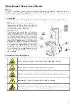
Page 3: ... of similar machi nes Any modifications not permitted by the manufacturer or not realised in accordance with the instructions for use and which go beyond the scope of this machine may lead to malfunctions and damage to the machine The manufacturer may then be relieved of its warranty obligation and coverage for the machine If for whatever reason machine parts are damaged please replace them in acc...

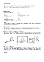
Page 4: ...or this purpose The already packed machine should only be loaded and unloaded with a sufficiently powerful forklift Fig 1 shows the exact position at which the forks should be inserted 5 Unpack checking for completeness and damage Pull out the nail attaching the plate with the top jaw Remove the cardboard and plastic cover Ensure that all parts listed on the spare parts list see item 14 of this ma...

Page 5: ...16A which should also correspond to the machine voltage Alternatively you can connect the machine directly to the power supply in accordance with the above specifications 9 Operating settings Jaw closing pedal H Jaw opening pedal V Turntable rotating pedal Z Levering pedal U 1 Press the turntable rotating pedal Z The turntable Y rotates in a clockwise direction Lift the turntable rotating pedal Z ...

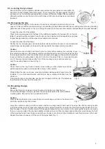
Page 6: ... the mounting head is about 2 3 mm from the edge of the rim Now insert the tyre iron T between the tyre bead and the front of the mounting head I and move the tyre over the mounting head as shown in Fig 6 Caution There should not be any chains buckles loose clothing or other objects near turned parts because they pose an increased risk of injury to the operator While holding the tyre iron in place...

Page 7: ...achine Please use a forklift or pallet truck to move the machine Disconnect the tyre changer from the power supply and the pneumatic connections raise the baseplate and insert the forklift pallet truck forks underneath Then anchor the tyre changer to its new location and fix it there Note The new location of the tyre changer should also meet safety requirements 12 Maintenance Caution Maintenance w...

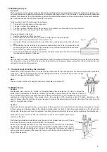
Page 8: ...n Please disconnect the machine from the power supply and the pneumatic connections Note Adjust the locking plate if the mounting arm cannot be secured or if it does not meet the requirement of being a distance of 2 3 mm from the edge of the rim Refer to Fig 12 in this respect and realise the adjustment X Note To ensure the reliability of the jaws and the bead breaker blade please proceed as follo...

Page 9: ...be engaged by locking plate Tighten screws replace locking plate Bead breaker blade and jaws opening clo sing pedals cannot be turned back to their original position Pedal spring damaged Replace pedal spring Bead breaker blade is difficult to handle Damper jammed Clean or replace Disc on bead breaker blade cylinder damaged Replace disc 14 Exploded view 201A 1 CX 201 010000 A Machine housing 300 10...

Page 10: ...ting dismounting head 137 B 014 100251 0 Hex screw M10x25 100 50 C 200 150100 5 Description mounting dismounting head 100 51 C 200 150300 1 Mounting dismounting head 100 52 C 200 150300 0 Front washer mounting dismounting head 141 B 007 120161 1 Hex socket screw M12x16 200 158D C 206 230200 D Cover locking handle D 200 160 CX 200 230000 0 Locking handle 200 161 CX 200 200000 0 Locking plat 200 162...

Page 11: ...out pin 200 222 C 200 100400 0 Threaded connecting rod 310 200 223 C 200 100200 0 Piston rod of clamping cy linder 320 224 C 200 100100 0 Clamping cylinder cover without handle 225 S 011 010808 0 Straight union 1 8 Ø8 226 S 005 020075 0 V seal 20 28 7 5 227 S 000 063265 0 O ring seal 63 2 65 228 C 200 540000 0 Piston with seal ring 229 B 040 122520 1 Flat washer Ø 12x24x2 230 B 004 120071 1 Nut M1...

Page 12: ...29 B 014 080201 0 Hex screw M8x20 311 S 005 168115 0 V seal 185x168x11 5 330 S 011 010808 0 Straight union 1 8 Ø8 200 312 C 200 050200 0 Tyre lever cylinder piston 331 S 000 019262 0 O ring seal Ø 19 6 x 2 62 200 313 CX 200 050300 0 Tyre lever cylinder tube 350 CW 112 209800 0 Tyre lever cylinder drain valve 314 B 010 060161 0 Hex socket screw M6x16 351 S 012 010808 0 Screw connection 90 1 8 Ø8 20...

Page 13: ...11 452 457 453 422 423 442 445 425 616 459 ...

Page 14: ...f locking nut M8 445 S 016 010808 2 Quick T connector 1 8 2 Ø 8 438 B 004 080001 0 Nut M8 206D 6 CX 206 060800 D Pedal support 439 C 200 370000 0 Pedal torsion spring 206D 1 CX 206 060000 D Complete pedal support 440 B 010 080501 0 Hex socket screw M8x50 4 B 010 060101 0 Hex socket screw M6x10 206D 4 CX 206 090000 D Pedal support for clamping cylinder S85 C 221 640000 S Pedal cover 433 B 040 03000...

Page 15: ...Cotter pin washer 14x40 521 S 000 030355 0 O ring seal Ø 30 3 55 200 522 C 200 320700 0 Oil resistant seal 200 526 CW 107 020001 0 Gearbox complete A04 S 015 000008 3 T screw connection 3 Ø 8 A44 B 010 060161 0 Hex socket screw M6x16 A48 S 017 010808 2 T screw connection 200 531 CZ 200 430100 0 Rotary valve housing 200 532 S 000 059262 0 O ring seal 59 9x2 62 200 535 CZ 200 430200 0 Rotary valve b...

Page 16: ...uter M8x35 612 B 004 080001 0 Nut M8 613 B 040 082220 1 Flat washer ȹ8x22x2 614 C 200 560000 0 Motor rubber buffer 200D CX 206 340000 D Motor support 616 CZ 000 205150 0 Motor cable 220V RVV5 1 0 617 B 050 080000 0 Spring washer Ø8 200 618 C 200 560000 0 Motor rubber buffer 200 504 C 200 320500 0 Gear tensioner U200 618 B 004 100001 0 Hex screw 512 B 014 100551 0 Hex screw outer M10 55 701 S 038 0...

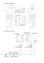
Page 17: ...15 15 Electrical circuit diagram 16 Pneumatic circuit diagram ...

Page 18: ...16 ...

Reviews: