


14
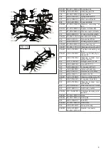
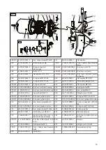
200-504 C-200-320500-0
Gear tensioner U200
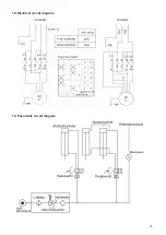
601-MY S-050-230075-0W Motor, tyre changer 220V-
240V/50Hz
200-602 CX-200-330000-0 Tensioner motor U200
603
B-007-080121-0
Hex. tensioning screw M8x12
604D
S-042-000620-0
Belt, tyre changer
605
B-014-080651-0
Hex. screw, outer M8x65
606
B-040-083030-1
Flat washer Ø8*30*3
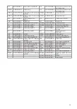
607-80
S-063-008000-0
Capacitor 80UF,110V
607-50
S-063-005000-0
Capacitor 50uf 220V
608
B-040-102020-1
Washer ȹ10*20*2
609
B-050-100000-0
Spring washer Ø10
610
B-014-100251-0
Hex. screw, outer M10x25
611
B-014-080351-0
Hex. screw, outer M8x35
612
B-004-080001-0
Nut M8
613
B-040-082220-1
Flat washer ȹ8x22x2
614
C-200-560000-0
Motor rubber buffer
200D
CX-206-340000-D Motor support
616
CZ-000-205150-0 Motor cable 220V RVV5*1.0
617
B-050-080000-0
Spring washer Ø8
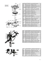
200-618 C-200-560000-0
Motor rubber buffer
200-504 C-200-320500-0
Gear tensioner U200
618
B-004-100001-0
Hex. screw
512
B-014-100551-0
Hex. screw, outer M10*55
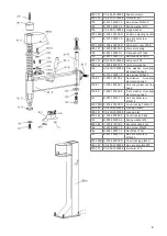
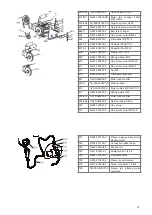
701
S-038-000100-0
Pressure gauge manual tyre
inflating meter
702
S-035-014150-1
Connection rubber hose
703
S-025-104008-0
Knurled nut
704
S-011-010414-1
Straight union 1/4-1/4
705
B-040-132420-1
Flat washer Ø13
706
S-030-010400-2
Pressure control valve
707
S-012-010408-0
Screw connection 1/4-Ø8
708
CW-090-000201-0
Manual tyre inflating meter
complete


