


4
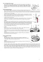
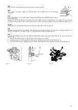
9.1. Levering the tyre bead
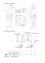
Ensure that the tyre is completely deflated and position the tyre against the stop buffer (S).
Now hold the bead breaker blade (R) approx. 10 mm away from the edge against the bead
as shown in Fig. 5. Press the levering pedal (U) to lever off the tyre. Repeat this procedure at
different positions around the tyre and on both sides until the tyre bead has been completely
loosened.
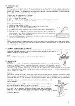
9.2. Removing the tyre
Ensure that all the weights on the wheel rim have been removed and allow all the air to es-
cape out of the tyre before you start working. Lubricate the tyre bead all around with tyre mounting paste. Not using mounting
paste can lead to heavy wear on the tyre. Clamp the wheel in the manner shown below corresponding to the wheel diameter.
To open the wheel from the outside:
Press the jaw opening pedal (V) halfway to the middle and position the four jaws (G) on the turn-
table (Y) using the reference scale. Place the tyre on the turntable, hold the edge firmly and press
the jaw closing pedal (H) until the wheel is securely fixed in the jaws.
To open the wheel from the inside:
Position the four clamping jaws (G) and keep them all closed. Place the tyre on the turntable and
press the jaw opening pedal (V) to open the clamps and fix the wheel securely in position.
Caution:
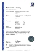
Ensure that the wheel is firmly anchored by the four jaws before realising the next step. Lower
the vertical mounting arm (M) manually until the mounting head (I) rests next to the edge, then flip
the locking handle (K) so that the vertical arm and rocker arm engage in their position. Adjust the
rocker so that the mounting head is about 2-3 mm from the edge of the rim. Now insert the tyre
iron (T) between the tyre bead and the front of the mounting head (I) and move the tyre
over the mounting head as shown in Fig. 6.
Caution:
There should not be any chains, buckles, loose clothing or other objects near turned
parts because they pose an increased risk of injury to the operator.
While holding the tyre iron in place, press the turntable rotating pedal (Z) and rotate the
turntable (Y) in a clockwise direction until the tyre has completely detached from the
wheel rim.
To remove the tyre on the other side, use the tyre iron again to lift the tyre. This detaches
the other side of the tyre from the wheel rim.
9.3. Mounting the tyre
Caution:
Ensure that the tyre and wheel rim are the same size before mounting the tyre.
To avoid any damage to the tyre, lubricate the tyre bead and wheel rim with a suitable
mounting paste. Now pull on the tyre and check its fit.
Caution:
When tightening the wheel rim, ensure that you avoid placing your hand on the wheel rim to
avoid any injuries during this process.
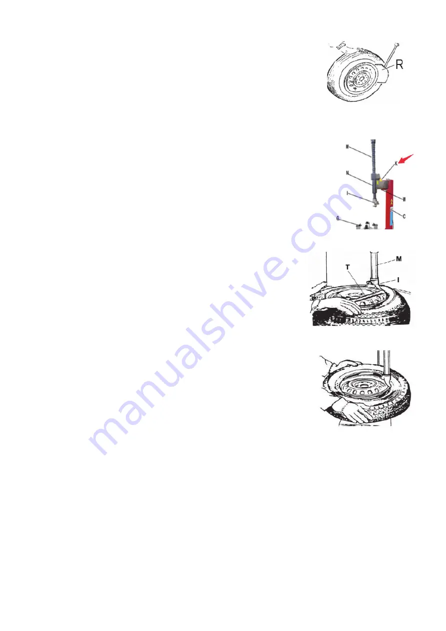
Lower the vertical mounting arm (M) manually until the mounting head (I) rests next to the edge, then flip the locking handle
so that the vertical arm and rocker arm engage in their position. Adjust the rocker so that the mounting head is about 2-3 mm
from the edge of the rim. Position the tyre at the edge and allow the tyre iron to return to the same position as when removing
the tyre. Lower one side of the tyre bead slightly until above the rear of the mounting head and the other side to below the front
of the mounting head. Press the tyre down with your hands or arm, then turn the turntable to push the tyre down on the bead.
Repeat the above procedure to fit the tyre to the upper bead (Fig. 7).
Fig. 5
Fig. 7
Fig. 6


