10/26/2005 BASIC
IF YOU HAVE ANY QUESTIONS PLEASE CALL JMR MANUFACTURING
PHONE: 805.
239.5972
FAX: 805.
239.5973
OPERATION OF THE BENDER
WARNING
This is a hand operated machine only.
Use of an impact wrench on the bender high/low drives will damage the internal drive
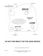
mechanism and WILL void the warranty.
1. Figure 1 is an overall view of the mechanical bender and a detail of the bender head.
2. The tubing should be clean and free from defects.
3. Always grease the die block prior to bending.
4. Make sure that all drive pins are fully seated.
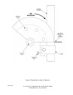
5. Pass tube into die and position as required for start of bend. All bends will start at the edge of
the radius die as shown in Figure 2.
6. Under normal use, the pivot bushings should be greased every 250-500 cycles. Under high use
conditions it will be necessary to grease the pivot bushings every month or more often as
necessary.
7. Install the U strap and snug retainer bolt if needed.
8. Make sure the release lever is in the UP position (CCW), See Figure 1.
9. Use of a 1/2" drive ratchet and a 3/4" socket is recommended to turn the bender drive
mechanism.
WARNING
Never put your hands or other body parts into bender apparatus.
10. The bender drive marked "HIGH" is for moving the drive rack fast or for bending lighter gauge
material.
11. The bender drive marked "LOW" is for moving the drive rack at a slow rate and is used for
bending heavier gauge material.
12. There is an approximate maximum of a 41º bend for each full stroke of the drive rack.
13. To bend tubing further than the 41º, the radius die must be indexed to the next drive hole.
14. Begin by first pulling and holding tension on the 1/2" ratchet in the direction of the bend. This
will remove tension on the drive mechanism release lever (See Figure 1).
15. While still holding tension on the 1/2" ratchet, pull the release lever down (CW). See Figure 1.
WARNING
On some materials there could be a large amount of "spring back" after a bend is made.
Please be aware that some materials could require as much as 1 to 1 1/2 turns
to release this spring back tension. For safety, control the rotation of the 1/2" ratchet
during the following steps.
16. SLOWLY release the tension on the 1/2" ratchet removing the pin when tension on the pin is
released and before the radius die starts to rotate.
17. Slowly retract the drive rack until the next radius die drive hole lines up with the pivot arm.
18. Re-install the pin fully and repeat the above bend process to complete the total bend.
19. Make sure the release lever is in the UP position (CCW), See Figure 1.
20. To repeat bends, without the degree wheel, measure the drive rack's total travel.

