14
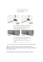
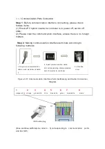
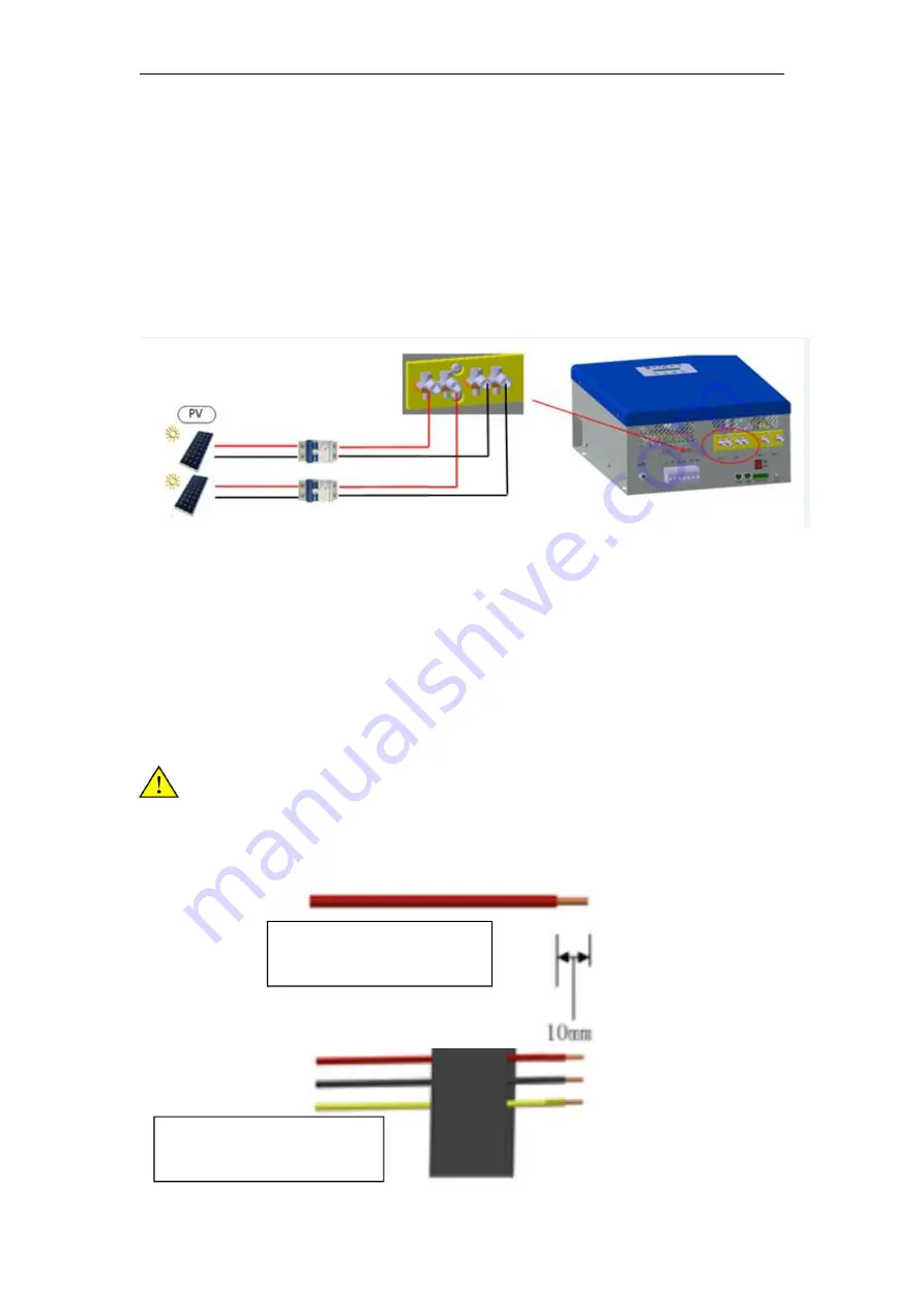
Figure 3-5 schematic diagram of photovoltaic terminal production and connection
Step 3
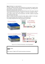
: During cable connecting of PV input side, insert PV cable of PV
array into auto Air-switch respectively according to positive pole and
negative pole; then insert the two cables which made in Step 2 into
Air-switch separately.
Step 4
: Check whether PV connecting is correct and firm.
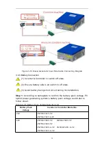
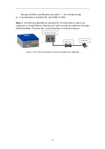
The cable connection diagram of PV input side is as follows:
Figure 3-6 PV Input Side Cable Connecting Diagram
3.4.2 AC Input Connection
Inverter & Controller can accept two kinds of AC power input, one is
single phase grid power, and another is single phase diesel generator
power. Please select corresponding connection mode according to the
specific connection.
3.4.2.1Grid Power Input connection
Please make sure Grid power in off state.
Step 1
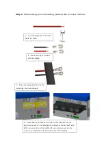
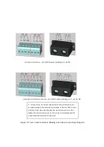
: Please according to follow methods, making Grid power side
cable connection and connectors.
1
、
Use stripping pliers to strip
the
cable for 10mm
2
、
Insert the finished cable
into the protective cover
Summary of Contents for JNF3KLF24V-A-V2
Page 4: ......


