24
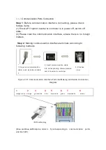
Orange & White and Brown(Line order 1
、
8) corresponding
to communication terminal 5V and GND of 485)
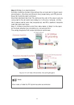
Step 3
: Connecting appliances needed for communication (such as
computer, communication module. etc) with inverter & controller through
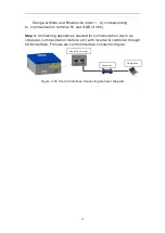
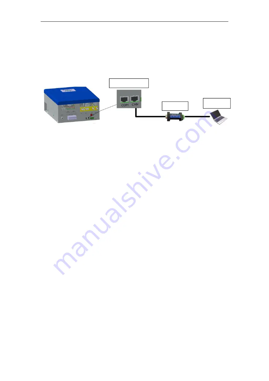
COM interface. Follows are control interface connection figure:
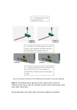
Figure 3-18 Control Interface Connecting General Diagram
Computer
Convertor
Control port input
Summary of Contents for JNF3KLF24V-A-V2
Page 4: ......


