35
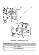
Table 6-5 COM terminal pin definitions on the machine panel
Signal Name
Description
VCC
+5V power source
A
RS48 Communication port A
B
RS485 Communication portB
GND
Grounding
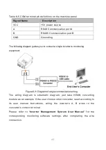
The following diagram guides you to connect a single inverter to monitoring
equipment.
Figure6-11 Diagram of single communication wiring
The wiring diagram is schematic diagram; just take HEXIN converting
module as an example. If the user choose other converter, need according to
its user manual instructions, wiring the inverter’s A, B wires to the
converter’s correct terminal.
Please refer to “
Inverter Management System User Manual
” for the
corresponding monitoring software settings, after completing the wire
connection.


