background image

CÓMO ELEGIR LA BOQUILLA

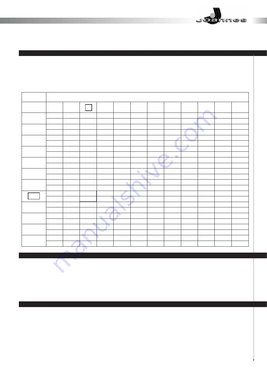
La boquilla se elige en función de la potencia de la cámara de combustión de la caldera, teniendo en cuenta que el
gasóleo tiene un poder calorífico inferior (P.C.I.) de 10200 kcal/kg. La tabla indica el caudal teórico o consumo (en
kg/h y en kW) de gasóleo en función del tamaño de la boquilla (GPH) y de la presión de la bomba (en bar). En los
quemadores de dos boquillas, el caudal se subdivide en forma indicativa entre el 40% en la boquilla de primera llama,
y el 60% en la segunda boquilla.

EJEMPLO DE CÓMO ELEGIR LA BOQUILLA

La caldera tiene una potencia de 290 kW en la cámara de combustión.
Para una presión en la bomba de 12 bar, el valor más cercano es de 288,80 kW, al que corresponde una boquilla
de 6 GPH. Si el quemador tiene dos boquillas, hay que dividir el caudal con una boquilla de 2,50 GPH en la primera
llama y de 3,50 GPH en la segunda. Si no es posible contar con una boquilla óptima se puede variar la presión de
la bomba, dentro de un límite de 11-14 bar, para obtener el caudal deseado.

MONTAJE DE LA BOQUILLA

Una vez que se ha elegido la boquilla que más conviene, se monta tal y como se indica en el apartado
“MANTENIMIENTO”.

PRESIÓN DE LA BOMBA bar (kg/cm

2

)

BOQUILLA

GPH

2,00

2,50

3,00

3,50

4,00

4,50

5,00

6,00

7,00

8,30

9,50

10,50

10

11

12

13

14

15

16

17

18

19

20

21

7,43

7,75

8,10

8,42

8,80

9,05

9,35

9,67

9,91

10,22

10,48

10,70

88,12

91,91

96,06

99,86

104,37

107,33

110,90

114,68

117,53

121,21

124,30

126,90

9,28

9,67

10,17

10,54

10,98

11,27

11,70

12,10

12,38

12,76

13,10

13,40

110,06

114,68

120,62

125,00

130,22

133,66

138,76

143,50

146,82

151,33

155,36

158,92

11,17

11,60

12,16

12,65

13,20

13,60

14,10

14,50

14,88

15,16

15,70

16,10

132,47

137,58

144,22

150,03

156,55

161,30

167,22

171,98

176,47

179,80

186,20

190,94

13,05

13,60

14,20

14,78

15,40

15,85

16,40

16,95

17,38

17,90

18,30

18,80

154,77

161,30

168,41

175,29

182,64

187,98

194,50

201,03

206,12

212,29

217,04

222,97

14,88

15,50

16,24

16,90

17,60

18,12

18,70

19,37

19,88

20,40

21,00

21,50

176,47

183,83

192,60

200,43

208,73

214,90

221,78

229,73

235,77

241,94

249,06

255,00

16,67

17,35

18,20

18,90

19,70

20,30

21,00

21,70

22,25

22,90

23,50

24,00

197,70

205,77

215,85

224,15

233,64

240,76

249,06

257,36

263,88

271,60

278,71

284,64

18,60

19,35

20,30

21,10

22,00

22,60

23,35

24,15

24,80

25,50

26,20

26,70

220,60

229,49

240,76

250,24

260,92

268,03

286,42

294,13

307,36

310,73

316,66

22,30

23,25

24,35

25,30

26,40

27,20

276,93

29,00

29,75

30,75

31,40

32,20

264,48

275,74

288,80

300,06

313,10

322,59

28,10

343,94

352,83

364,49

372,40

381,90

26,00

27,15

28,40

29,50

30,70

31,70

333,26

33,90

34,80

35,80

36,65

37,50

308,36

322,00

336,82

349,87

364,10

375,96

32,70

402,05

412,73

424,59

434,67

444,75

30,80

32,10

33,60

34,90

36,40

37,50

387,82

40,20

365,29

380,70

398,50

413,91

431,70

444,75

38,75

476,77

35,30

36,70

38,50

40

45957

418,66

435,26

456,61

474,4

39,00

40,65

462,54

482,11

pág. 96

Summary of Contents for G50/2 oil

Page 1: ...DOS EM QUALQUER MOMENTO E SEM AVISO PR VIO 97 00302 0 Selecta Vi 0444352000 FINTERM S p A CORSO ALLAMANO 11 10095 GRUGLIASCO TO TEL 011 4022 1 FAX 011 780 40 59 w w w j o a n n e s i t i n f o j o a n...

Page 2: ...LO 19 IRREGOLARIT DI FUNZIONAMENTO 20 MANUALE PER L UTENTE 21 NORME GENERALI 21 DESCRIZIONE 23 IRREGOLARIT DI FUNZIONAMENTO 24 NOMENCLATURA CODICI 26 ESPLOSI RICAMBI 28 GENTILE CLIENTE La ringraziamo...

Page 3: ...UNI EN ISO 9001 pag 2 FINTERM S p A una delle primissime aziende italiane alla quale stata riconosciuta la certificazione del proprio sistema qualit secondo la normativa internazionale...

Page 4: ...3 I bruciatori a gasolio G50 2 oil G70 2 oil hanno superato i test di omologazione europei e sono in linea con le pi restrittive norme in fatto di sicurezza e rendimento DICHIARAZIONE DI CONFORMIT CE...

Page 5: ...pag 4 ALLEGATO DI DICHIARAZIONE ALLA CONFORMIT...

Page 6: ...lorch si decida di non utilizzare pi l apparecchio si dovranno rendere innocue quelle parti che possono diventare potenziali fonti di pericolo Prima di avviare il bruciatore far verificare da personal...

Page 7: ...cavi del neutro con i cavi della fase Il bruciatore pu essere allacciato alla rete elettrica con un collegamento spina presa solamente se questo risulti dotato in modo tale per cui la configurazione...

Page 8: ...parzializzatrice sulla mandata della ventola Questo sistema permette di ottenere sempre le migliori condizioni di pressione portata aria in tutto il campo di lavoro del bruciatore per realizzare combu...

Page 9: ...776 169 000 667 600 16 6 27 65 4 12 59 1 500 2 7 4 4 12 35 1 900 Motorizzata 2 Potenza termica min max min max Consumo combustibile min max Pompa combustibile Combustibile Peso Motore Protettore Termi...

Page 10: ...ore della caldaia Stringere la vita 1 per bloccare il bruciatore Le dimensioni sono orientative essendo influenzate da eccesso di aria forma camera di combustione sviluppo giri fumo della caldaia dire...

Page 11: ...ento di terra rispettare le norme della buona tecnica ed osservare scrupolasamente le norme locali vigen 1 Apparecchiatura aut di comando 2 3 Comando a distanza funz min max 4 Comando funzionamento mi...

Page 12: ...di blocco ed una di non ritorno ALIMENTAZIONE GASOLIO Si raccomanda di evitare per quanto possibile questa soluzione poich noto che essa pu originare notevoli disfunzioni al bruciatore se non realizz...

Page 13: ...8 117 53 121 21 124 30 126 90 9 28 9 67 10 17 10 54 10 98 11 27 11 70 12 10 12 38 12 76 13 10 13 40 110 06 114 68 120 62 125 00 130 22 133 66 138 76 143 50 146 82 151 33 155 36 158 92 11 17 11 60 12 1...

Page 14: ...DEFLETTORE Dopo aver montato l ugello o gli ugelli verificare il corretto posizionamento degli elettrodi e deflettore secondo le quote riportate mm E opportuno eseguire una verifica delle quote dopo o...

Page 15: ...azionata dal motoriduttore La regolazione delle posizioni chiuso aperto 1a fiamma aperto max si effettua sulle camme girando in senso antiorario per aumentare l apertura della serranda ed in senso ora...

Page 16: ...mette in rotazione insieme con la pompa il gasolio aspirato viene totalmente inviato verso il ritorno Sono in funzione anche il ventilatore del bruciatore ed il trasformatore d accensione per cui si e...

Page 17: ...one fiamma determiner il funzionamento alta bassa fiamma D Se entro il tempo di sicurezza non si ha il segnale di fiamma l apparecchiatura toglie corrente al motore alla valvola VE1 ed al trasformator...

Page 18: ...la temperatura maggiori sono le dispersioni e pi basso il rendimento di combustione Con i bruciatori funzionanti ad alta bassa fiamma necessario accertarsi che non si creino le condizioni per la cond...

Page 19: ...zione della piastra superiore FOTORESISTENZA Sfilarla dalla sua sede e pulire la sua parte sensibile con un panno asciutto FILTRO POMPA Chiudere la saracinesca sull aspirazione smontare il coperchio d...

Page 20: ...a con il gruppo flangia ugello deflettore elettrodi ELETTRODI UGELLO Svitare le viti 5 per togliere il deflettore e le viti 6 per togliere gli elettrodi Una buona pulizia dell ugello si ottiene smonta...

Page 21: ...a C C acqua nel gasolio A Ugello polverizza male B Poca aria di combustione A Controllare i fusibili B Controllare i termostati ambiente caldaia e sicurezza C Controllare la linea di alimentazione A V...

Page 22: ...nale professionalmente qualificato la manuntenzione periodica dell apparecchio Allorch si decida di non utilizzare pi l apparecchio si dovranno rendere innocue quelle parti che possono diventare poten...

Page 23: ...mai i cavi del neutro con i cavi della fase Il bruciatore pu essere allaciato alla rete elettrica con un colegamento spina presa solamente se questo risulti dotato in modo tale per cui la configurazio...

Page 24: ...chiatura inizier il test di autoverifica dopo di che il bruciatore si accender automaticamente Qualora l accensione non si verificasse pulsante di blocco acceso premerlo in modo che l apparecchiatura...

Page 25: ...pag 24 G 50 2 oil G 70 2 oil...

Page 26: ...ATTENZIONE IN CASO DI PERICOLO TOGLIERE CORRENTE DALL INTERRUTTORE GENERALE E CHIUDERE L AFFLUSSO DI COMBUSTIBILE TRAMITE L APPOSITA SARACINESCA IT G 50 2 oil G 70 2 oil pag 25...

Page 27: ...SSURIZZAZIONE LAVORATO 271574 271574 23 ANELLO ENTRATA ARIA 271519 271519 24 INSIEME TUBO MANDATA 1 STADIO 274840 274842 25 INSIEME TUBO MANDATA 2 STADIO 274844 274846 26 POMPA 995859 995859 27 INSIEM...

Page 28: ...BILE ASPIRAZIONE 29852 429852 54 55 56 57 58 59 ZOCCOLO CON PREMISTOPPA 997739 997739 60 APPARECCHIO DI CONTROLLO 997741 997741 61 62 63 64 65 66 67 SUPPORTO PASSACAVI 273110 273110 68 PIASTRA SUPPORT...

Page 29: ...stenza sporca B Ugello che polverizza male A Ugello polverizza male B La pressione in pompa troppo bassa C C acqua nel gasolio A Ugello polverizza male B Poca aria di combustione A Controllare i fusib...

Page 30: ...N 46 ELECTRODES GICLEUR 47 ANOMALIES DE FONCTIONNEMENT 48 NOTICE POUR L UTILISATEUR 49 NORMES GENERALES 49 DESCRIPTION 51 ANOMALIES DE FONCTIONNEMENT 52 NOMENCLATURE REFERENCES 54 VUES ECLATEES DES PI...

Page 31: ...UNI EN ISO 9001 pag 30 FINTERM S p A est l une des toutes premi res soci t s italiennes ayant b n fici de la certification du propre syst me de qualit d apr s la r glementation internationale...

Page 32: ...br leurs fioul lourd G 50 2 oil G 70 2 oil ont pass les tests d homologation europ ens et sont conformes aux normes les plus restrictives concernant la s curit et le rendement DECLARATION DE CONFORMI...

Page 33: ...pag 32 ANNEXE A LA DECLARATION DE CONFORMITE...

Page 34: ...nnel professionnellement qualifi Si vous d cidez de ne plus utiliser l appareil il faudra neutraliser les pi ces pouvant constituer un danger Avant de mettre le br leur en marche faire v rifier par un...

Page 35: ...par un personnel qualifi Ne jamais inverser les c bles du neutre et les c bles de la phase Le br leur ne peut tre connect au r seau lectrique par une fiche de connexion que si la configuration de l ac...

Page 36: ...envoi du ventilateur Ce syst me permet d obtenir toujours les meilleures conditions de pression d bit d air dans toute la plage de travail du br leur pour r aliser des combustions faible exc s d air h...

Page 37: ...4 4 12 35 1 500 Motoris 2 197 776 169 000 667 600 16 6 27 65 4 12 59 1 500 2 7 4 4 12 35 1 900 Motoris 2 Puissance thermique min max min max Consommation min combustible max Pompe combustible Combust...

Page 38: ...Serrer la vis 1 pour bloquer le br leur Les dimensions sont titre indicatif car elles d pendent de l exc s d air de la forme de la chambre de combustion du type de parcours des fum es de la chaudi re...

Page 39: ...ectuer une installation de mise terre efficace Respecter les r gles techniques et observer formellement les normes locales en vigueur 1 Coffret de s curit 2 3 Commande distance fonctionnement min max...

Page 40: ...N AU FIOUL DOMESTIQUE Nous recommandons d viter si possible cette solution car il est bien connu que cela peut causer d importants mauvais fonctionnements au br leur si cette alimentation n est pas fa...

Page 41: ...0 22 10 48 10 70 88 12 91 91 96 06 99 86 104 37 107 33 110 90 114 68 117 53 121 21 124 30 126 90 9 28 9 67 10 17 10 54 10 98 11 27 11 70 12 10 12 38 12 76 13 10 13 40 110 06 114 68 120 62 125 00 130 2...

Page 42: ...voir mont le gicleur ou les gicleurs v rifier la bonne position des lectrodes et du d flecteur en fonction des cotes indiqu es mm Il convient de v rifier la bonne position des lectrodes apr s toute in...

Page 43: ...r glage des positions ferm ouvert de la 1 re allure ouverture maximale s effectue sur les cames en tournant dans le sens contraire des aiguilles d une montre pour augmenter l ouverture du clapet de l...

Page 44: ...Le moteur du br leur se met tourner avec la pompe le fioul domestique aspir est compl tement envoy vers le retour Le ventilateur du br leur et le transformateur d allumage fonctionnent galement et le...

Page 45: ...ulation de la flamme intervient alors et d termine le fonctionnement haute basse flamme D Si le signal de flamme n a pas lieu dans le temps de s curit le coffret de s curit coupe le courant au moteur...

Page 46: ...e plus les d perditions sont importantes et le rendement de combustion faible Lorsque les br leurs fonctionnent haute basse flamme s assurer que le milieu ne soit pas propice la condensation des fum...

Page 47: ...pr vue cet effet PHOTORESISTANCE Retirer la photor sistance de son logement et nettoyer la partie sensible avc un chiffon sec FILTRE DE LA POMPE Fermer le clapet d aspiration ter le couvercle de la p...

Page 48: ...retirer avec le groupe bride gicleur d flecteur lectrodes ELECTRODES GICLEUR D visser les vis 5 pour ter le d flecteur et les vis 6 pour ter les lectrodes Afin de pouvoir bien nettoyer le gicleur d mo...

Page 49: ...le C Pr sence d eau dans le fioul A Mauvaise pulv risation au gicleur B Combustion peu ventil e A Contr ler les fusibles B Contr ler les thermostats ambiance chaudi re s curit C Contr ler la ligne d a...

Page 50: ...ofessionnellement qualifi Si vous decidez de ne plus utiliser l appareil il faudra neutraliser les pi ces pouvant constituer un danger Avant de mettre le br leur en marche faire v rifier par un person...

Page 51: ...ualifi Ne jamais inverser les c bles du neutre et les c bles de la phase Le br leur ne peut tre connect au r seau lectrique par une fiche de connexion que si la configuration de l accouplement est pr...

Page 52: ...ffret de s curit effectuera le test d auto contr le puis le br leur s allumera automatiquement Si l allumage ne se fait pas et que le poussoir d arr t est allum appuyer sur ce dernier de mani re ce qu...

Page 53: ...pag 52 G 50 2 oil G 70 2 oil...

Page 54: ...ATTENTION EN CAS DE DANGER COUPER L ALIMENTATION ELECTRIQUE A L AIDE DE L INTERRUPTEUR GENERAL ET COUPER L ARRIVEE DE COMBUSTIBLE A L AIDE DU ROBINET VANNE SPECIFIQUE F R G 50 2 oil G 70 2 oil pag 53...

Page 55: ...E PRESSURISATION USINEE 271574 271574 23 BAGUE DE L ENTREE D AIR 271519 271519 24 ENSEMBLE DU TUBE DE REFOULEMENT 1ER ETAGE 274840 274842 25 ENSEMBLE DU TUBE DE REFOULEMENT 2E ETAGE 274844 274846 26 P...

Page 56: ...9852 54 55 56 57 58 59 SOCLE AVEC PRESSE ETOUPE 997739 997739 60 APPAREIL DE CONTROLE 997741 997741 61 62 63 64 65 66 67 SUPPORT DU PASSAGE DES CABLES 273110 273110 68 PLAQUE DE SUPPORT DU TABLEAU TEC...

Page 57: ...Mauvaise pulv risation au gicleur A Mauvaise pulv risation au gicleur B La pression de la pompe est trop faible C Pr sence d eau dans le fioul A Mauvaise pulv risation au gicleur B Combustion peu ven...

Page 58: ...4 ELECTRODES NOZZLE 75 BREAKDOWN SEARCH 76 INSTRUCTIONS FOR THE USER 77 GENERAL 77 DESCRIPTION 79 BRAKDOWN SEARCH 80 NOMENCLATURE CODES 82 DIAGRAM SPARE PARTS 84 DEAR CUSTOMER We thank you for the pre...

Page 59: ...UNI EN ISO 9001 pag 58 FINTERM S p A has been one of the first Italian companies to receive the certification of its quality systems according to the international standards...

Page 60: ...pag 59 The light oil brumers G50 2 oil G70 2 oil have passed the European certification tests and are in compliance with the strictest rules as to safety and efficiency CE CONFORMITY DECLARATION GB...

Page 61: ...pag 60 ANNEX TO THE CONFORMITY DECLARATION...

Page 62: ...make sure that a the supply and electric system is adequate for the unit rated input shown on the data plate b the settings of the burner is adequate for the boiler power c the combustion air intake...

Page 63: ...such in a way that the configuration of the coupling prevents the reversal of the phase and of the neutral Install a service switch in the control panel for the heating unit in compliance whit the cur...

Page 64: ...tem permits to obtain the best conditions of pressure air flow on the whole working filed of the burner and achieve low air excess high efficiency and high mixing energy combustion with a low contents...

Page 65: ...red 2 197 776 169 000 667 600 16 6 27 65 4 12 59 1 500 2 7 4 4 12 35 1 900 Powered 2 Thermal power min max min max Fuel Consuption min max Fuel pump setting pressure Fuel light oil Weight Motor Therma...

Page 66: ...boiler manufacturer Tighten the screw 1 to block the burner The dimensions are indicative They may be influenced by Excess of air The shape of the combustion chamber Development of smoke turns of the...

Page 67: ...r each terminal Warnings Do not exchange the neutral with the phase Carry out a good earthing Respect the regulations in force 1 Automatic control devices 2 3 Min max working remote control 4 Min max...

Page 68: ...lbows an action valve and a non return valve LIGHT OIL SUPPLY It s recommended to avoid this solution as it might originate remarkable troubles to the burner should it not perfectly realised If howeve...

Page 69: ...110 90 114 68 117 53 121 21 124 30 126 90 9 28 9 67 10 17 10 54 10 98 11 27 11 70 12 10 12 38 12 76 13 10 13 40 110 06 114 68 120 62 125 00 130 22 133 66 138 76 143 50 146 82 151 33 155 36 158 92 11 1...

Page 70: ...DEFLECTOR After installing the nozzle or the nozzles check the proper positioning of the electrodes and of the deflector according to the reported data mm It is recommended to proceed to a check of th...

Page 71: ...er is operated by the gearmotor The adjustment of the positions closed open 1st flame box opening is effected on the cams by turning counterclockwise to increase the opening of the air shutter and clo...

Page 72: ...ong with the pump the light oil is totally sent towards the return pipe The burner fan and the ignition transformer are also operating and the following phases are taking place pre ventilation of the...

Page 73: ...will determine the high low flame operation C If there is no flame signal within safety time the device interrupts the current to the motor to the valve VE1 and to the transformer and moves on the pos...

Page 74: ...the higher the temperature the greater the dispersions and the lower the combustion efficiency When the burners are operating with high low flame it is necessary to make sure that the conditions for t...

Page 75: ...he nozzle electrodes the end plate is usually pulled out by the removal of the upper plate PHOTORESISTOR Remove it from its seat and clean the sensitive portion by a dry cloth PUMP FILTER Close the ga...

Page 76: ...nd pull it out with the set flange nozzle deflector electrodes ELETRODES NOZZLE Loosen the screws 5 to remove the deflector and loosen screws 6 to remove the electrodes Clean the nozzle by removing th...

Page 77: ...the pump is too low C There is water in the light oil A The nozzle does not atomise properly B Poor combustion air A Check the fuses B Check the thermostats ambient boiler and safety C Check the feedi...

Page 78: ...ersonnel to check that a the plate data are those required from the electric and fuel supply system b the setting of the burner is adequate to the power of the boiler c the combustion air flow and the...

Page 79: ...of the phase and of the neutral Install a service switch in the control panel for the heating unit as required from the current regulation The whole electric system and all the sections of the cables...

Page 80: ...red temperature on the adjustable thermostat of the boiler The unit will start the self test then the burner will automatically start Should the starting not occur with the block botton on push it so...

Page 81: ...pag 80 G 50 2 oil G 70 2 oil...

Page 82: ...WARNING IN CASE OF DANGER TURN OFF THE SYSTEM SWITCH AND STOP THE FUEL INFLOW BY THE PROPER SHUTTER GB G 50 2 oil G 70 2 oil pag 81...

Page 83: ...SHED PRESURISATION RING 271574 271574 23 AIR INLET RING 271519 271519 24 SET INLET PIPE 1ST STAGE 274840 274842 25 SET INLET PIPE 2ND STAGE 274844 274846 26 PUMP 995859 995859 27 SET NOZZLE SUPPORT CA...

Page 84: ...BLE INTAKE HOSE 429852 429852 54 55 MOTOR PUMP COUPLING 233802 27319556 56 57 58 59 BASE WITH COUPLING 997739 997739 60 CONTROL UNIT 997741 997741 61 62 63 64 65 66 67 CORE HITCH SUPPORT 273110 273110...

Page 85: ...es not atomise properly A The nozzle does not atomise properly B The pressure in the pump is too low C There is water in the light oil A The nozzle does not atomise properly B The combustion air is in...

Page 86: ...ODOS BOQUILLA 103 IRREGULARIDADES EN EL FUNCIONAMIENTO 104 MANUAL PARA EL USUARIO 105 NORMAS GENERALES 105 DESCRIPCI N 107 IRREGULARIDADES DE FUNCIONAMIENTO 108 DESCRIPCI N DE LOS REPUESTOS 110 DIBUJO...

Page 87: ...UNI EN ISO 9001 p g 86 FINTERM S p A es una de las primeras empresas italianas que ha obtenido la certificaci n del propio sistema de calidad seg n la normativa internacional...

Page 88: ...87 Los quemadores de gas leo G50 2 oil G70 2 oil han superado las pruebas europeas de homologaci n y se ajustan a las m s restrictivas normas de seguridad y rendimiento DECLARACI N DE CONFORMIDAD CE...

Page 89: ...p g 88 ANEXO A LA DECLARACI N DE CONFORMIDAD...

Page 90: ...l quemador Si se decidiera no utilizar m s el quemador habr a que hacer que sean inocuas las partes que podr an convertirse en potenciales fuentes de peligro Antes de poner en marcha el quemador el pe...

Page 91: ...os de la fase El quemador se puede conectar a la corriente con un conector clavija enchufe solamente si este tipo de conexi n est hecha de manera que se evite la posibilidad de invertir la fase y el n...

Page 92: ...Este sistema permite obtener siempre las mejores condiciones de presi n caudal del aire en todo el campo de trabajo del quemador para obtener combustiones con bajo exceso de aire de elevado rendimien...

Page 93: ...da 2 197 776 169 000 667 600 16 6 27 65 4 12 59 1 500 2 7 4 4 12 35 1 900 Motorizada 2 Potencia t rmica m n m x m n m x Consumo de combustible m n m x Bomba del combustible Combustible Peso Motor Prot...

Page 94: ...e el tornillo 1 para bloquear el quemador Las dimensiones son indicativas pues dependen de varios factores del exceso de aire de la forma de la c mara de combusti n de la forma del paso de humos de la...

Page 95: ...e Efect e una conexi n de tierra correcta Respete las normas t cnicas y las normas locales vigentes 1 Caja aut de control 2 3 Mando a distancia funcionamiento m n m x 4 Mando funcionamiento m n m x 5...

Page 96: ...de una antirretroceso ALIMENTACI N CON GAS LEO Se aconseja evitar lo m s posible este tipo de alimentaci n pues como ya se sabe puede originar problemas considerables al quemador si no se hace de mane...

Page 97: ...91 10 22 10 48 10 70 88 12 91 91 96 06 99 86 104 37 107 33 110 90 114 68 117 53 121 21 124 30 126 90 9 28 9 67 10 17 10 54 10 98 11 27 11 70 12 10 12 38 12 76 13 10 13 40 110 06 114 68 120 62 125 00 1...

Page 98: ...espu s de haber montado la boquilla o las boquillas controle el funcionamiento correcto de los electrodos y del disco deflector seg n los valores indicados mm Es conveniente efectuar un control de los...

Page 99: ...rreductor La regulaci n de las posiciones de abierto cerrado y de 1 llama abierto m x se hace girando las levas en el sentido contrario de las agujas del reloj para aumentar la apertura de la clapeta...

Page 100: ...or del quemador se pone a girar junto con la bomba el gas leo aspirado se env a totalmente hacia el retorno Funcionan tambi n el ventilador del quemador y el transformador de encendido y se efect an l...

Page 101: ...llama determina el funcionamiento con alta baja llama D Si dentro del tiempo de seguridad no se obtiene la se al de llama la caja de control quita corriente al motor a la v lvula VE1 al transformador...

Page 102: ...atura mayores son las dispersiones y m s bajo es el rendimiento de combusti n Con los quemadores que funcionan con alta baja llama es necesario asegurarse de que no se creen condiciones para la conden...

Page 103: ...el grupo de la cabeza quitando la placa superior FOTORRESISTENCIA S quela de su alojamiento y limpie la parte sensible con una pa o h medo FILTRO DE LA BOMBA Cierre la llave de corte en la aspiraci n...

Page 104: ...el grupo brida boquilla deflector electrodos ELECTRODOS BOQUILLA Destornille los tornillos 5 para quitar el deflector y los tornillos 6 para quitar los electrodos Una buena limpieza de la boquilla se...

Page 105: ...lla pulveriza mal B Hay poco aire de combusti n A Controlar los fusibles B Controlar los termostatos ambiente caldera y seguridad C Controlar la l nea de alimentaci n A Controlar si la posici n de las...

Page 106: ...decidiera no utilizar m s el quemador habr a que hacer que sean inocuas las partes que podr an convertirse en potenciales fuentes de peligro Antes de poner en marcha el quemador el personal t cnico c...

Page 107: ...neutro con los de la fase El quemador se puede conectar a la corriente con una conexi n clavija enchufe solamente si este tipo de conexi n evita la posibilidad de invertir la fase y el neutro Instale...

Page 108: ...r a efectuar la prueba de autocomprobaci n y despu s el quemador se encender autom ticamente Si no se encendiera con el bot n de bloqueo encendido presi nelo de manera que la caja de control repita la...

Page 109: ...p g 108 G 50 2 oil G 70 2 oil...

Page 110: ...CI N EN CASO DE PELIGRO DESCONECTE EL APARATO DE LA CORRIENTE MEDIANTE EL INTERRUPTOR GENERAL Y CIERRE LA APORTACI N DE COMBUSTIBLE MEDIANTE LA LLAVE DE CORTE A TAL EFECTO ES G 50 2 oil G 70 2 oil p g...

Page 111: ...23 ANILLO ENTRADA AIRE 271519 271519 24 CONJUNTO TUBO IDA 1 ETAPA 274840 274842 25 CONJUNTO TUBO IDA 2 ETAPA 274844 274846 26 BOMBA 995859 995859 27 CONJUNTO TUBO PORTABOQUILLA 1 ETAPA 274820 274821...

Page 112: ...2S 52 53 TUBO FLEXIBLE ASPIRACI N 429852 429852 54 55 56 57 58 59 BASE CON PRENSAESTOPAS 997739 997739 60 CAJA DE CONTROL 997741 997741 61 62 63 64 65 66 67 SOPORTE PASACABLES 273110 273110 68 BRIDA S...

Page 113: ...illa pulveriza mal A La boquilla pulveriza mal B La presi n en la bomba es demasiado baja C Hay agua en el gas leo A La boquilla pulveriza mal B Hay poco aire de combusti n A Controlar los fusibles B...

Page 114: ...A 131 IRREGULARIDADE DE FUNCIONAMENTO 132 MANUAL PARA O USU RIO 133 NORMAS GERAIS 133 DESCRI O 135 IRREGULARIDADE DE FUNCIONAMENTO 136 NOMENCLATURA 138 VISTA DETALHADA DAS PE AS DE REPOSI O 140 PREZAD...

Page 115: ...UNI EN ISO 9001 p g 114 FINTERM S p A uma das primeiras empresas italianas ao qual foi reconhecida a certifica o do pr prio sistema de qualidade conforme a normativa internacional...

Page 116: ...115 Os queimadores a g s G50 2 oil G70 2 oil superaram os testes de homologa o europeus e est o em linha com as mais restritivas normas em fato de seguran a e rendimento DECLARA O DE CONFORMIDADE CE...

Page 117: ...ANEXO DE DECLARA O CONFORMIDADE p g 116...

Page 118: ...elho No momento em que se decida de n o utilizar mais o aparelho necess rio tornar in cuas as potenciais fontes de perigo Antes de ligar o queimador fazer controlar pelo pessoal qualificado a que os d...

Page 119: ...cabos de neutro com os cabos da fase O queimador pode ser conectado rede el trica com uma liga o tomada plugue somente se este resulte dotado em modo tal que a configura o do acoplamento possa preven...

Page 120: ...divisor na vaz o da ventoinha Este sistema permite de obter sempre as melhores condi es de press o vaz o do ar em todo o campo de trabalho do queimador para realizar combust es baixo excesso de ar al...

Page 121: ...7 776 169 000 667 600 16 6 27 65 4 12 59 1 500 2 7 4 4 12 35 1 900 Motorizada 2 Pot ncia T rmica m n m x m n m x Consumo combust vel m n m x Bomba Combust vel Combust vel Peso Motor Protetor T rmico T...

Page 122: ...Apertar o parafuso 1 para bloquear o queimador As dimens es s o indicativas sendo influenciadas pelo excesso de ar forma da c mera de combust o desenvolvimento giros dos vapores da caldeira direto re...

Page 123: ...m a fase executar uma boa liga o de terra respeitar as normas da boa t cnica e observar atenciosamente as normas locais em vigor 1 Aparelhagem aut de comando 2 3 Comando dist ncia funcionamento min m...

Page 124: ...lvula de bloqueio e uma de n o retorno ALIMENTA O GAS LEO aconselh vel evitar por quanto possa ser poss vel esta solu o pois noto que esta pode dar origem a not veis disfun es ao queimador se n o real...

Page 125: ...121 21 124 30 126 90 9 28 9 67 10 17 10 54 10 98 11 27 11 70 12 10 12 38 12 76 13 10 13 40 110 06 114 68 120 62 125 00 130 22 133 66 138 76 143 50 146 82 151 33 155 36 158 92 11 17 11 60 12 16 12 65...

Page 126: ...DEFLETOR Ap s haver montado a tubeira ou as tubeiras verificar o correto posicionamento dos eletrodos e do defletor conforme as cotas mostradas mm oportuno executar uma verifica o das cotas ap s cada...

Page 127: ...por um motoredutor A regulagem das posi es fechado aberto 1 chama aberto max se efetua sobre as cames girando no sentido anti hor rio para aumentar a abertura do registro e no sentido hor rio para di...

Page 128: ...se coloca em rota o junto com a bomba o gas leo aspirado vem totalmente enviado em dire o ao retorno Est o funcionando tamb m o ventilador do queimador e o transformador de liga o para o qual se efetu...

Page 129: ...ma ir determinar o funcionamento chama alta baixa B Se entre o tempo de seguran a n o se obt m o sinal da chama a aparelhagem retira a corrente ao motor v lvula VE1 e ao transformador e se coloca em p...

Page 130: ...alta for a temperatura maiores s o as dispers es e mais baixo o rendimento de combust o Com o queimador em fun o alta baixa chama necess rio assegurar se que n o se criam condi es para a condensa o do...

Page 131: ...te atrav s da remo o da chapa superior FOTO RESIST NCIA Extrair da sua sede e limpar a sua parte sens vel com um peda o de pano enxuto FILTRO DA BOMBA Fechar o registro na aspira o desmontar a tampa d...

Page 132: ...or e extrair la com o grupo flange tubeira defletor eletrodos ELETRODOS TUBEIRA Desparafusar os parafusos 5 para retirar o defletor e os parafusos 6 para retirar os eletrodos Uma boa limpeza da tubeir...

Page 133: ...C Tem gua no gas leo A A tubeira executa uma mau pulveriza o B Pouco ar de combust o A Controlar os fus veis B Controlar os termostatos ambiente caldeira e seguran a C Controlar a linha de alimenta o...

Page 134: ...mento em que se decida de n o utilizar mais o aparelho necess rio tornar in cuas as potenciais fontes de perigo Antes de ligar o queimador fazer controlar pelo pessoal qualificado a que os dados da pl...

Page 135: ...cabos de neutro com os cabos da fase O queimador pode ser conectado rede el trica com uma liga o tomada plugue somente se este resulte dotado em modo tal que a configura o do acoplamento possa preven...

Page 136: ...teste de autoverifica o e logo ap s o queimador se acender automaticamente Se caso n o se verificasse a liga o com o bot o de bloqueio aceso pressionar lo em modo que a aparelhagem repita o teste de...

Page 137: ...p g 136 G 50 2 oil G 70 2 oil...

Page 138: ...ATEN O EM CASO DE PERIGO RETIRAR A CORRENTE AO INTERRUPTOR GERAL E FECHAR O AFLUXO DE COMBUST VEL ATRAV S DO ADEQUADO REGISTRO P T G 50 2 oil G 70 2 oil p g 137...

Page 139: ...RIZA O TRABALHADO 271574 271574 23 ANEL ENTRADA AR 271519 271519 24 CONJUNTO TUBO VAZ O 1 FASE 274840 274842 25 CONJUNTO TUBO VAZ O 2 FASE 274844 274846 26 BOMBA 995859 995859 27 CONJUNTO ESTOJO PORTA...

Page 140: ...EX VEL ASPIRA O 429852 429852 54 55 56 57 58 59 BASE COM CAIXA DE EMPANQUE 997739 997739 60 APARELHO DE CONTROLE 997741 997741 61 62 63 64 65 66 67 SUPORTE PASSAGEM CABOS 273110 273110 68 CHAPA SUPORT...

Page 141: ...ja B A tubeira executa uma mau pulveriza o A A tubeira executa uma mau pulveriza o B A press o na bomba muito baixa C Tem gua no gas leo A A tubeira executa uma mau pulveriza o B Pouco ar de combust o...

Page 142: ......

Page 143: ......

Page 144: ......

Page 145: ......

Page 146: ......

Page 147: ......

Page 148: ......

Page 149: ......

Page 150: ......

Page 151: ...PA INO 0 1 2 3 4 5 6 7 8 9 T N Ph...

Page 152: ......

Page 153: ......

Page 154: ......

Page 155: ......

Page 156: ......

Page 157: ......

Page 158: ......

Page 159: ......

Page 160: ......

Page 161: ......

Page 162: ......

Page 163: ......

Page 164: ......

Page 165: ......

Page 166: ......

Page 167: ......

Page 168: ......

Page 169: ......

Reviews: