6
Hoyer
®
Switch
Brake Pedal/Pad
Removal
1.
Unscrew the right hand brake lever M8 domed securing nut using a 14mm A/F combination wrench.
2. Withdraw the brake lever, brake lever securing bolt, nylon bush and brake pad spring from the hole in
the base.
3.
Remove the retaining circlip from the rear of the right hand brake pad spindle using a large (7mm) flat
blade screwdriver.
Replacement
NOTE:
Prior to re-assembly of the brake pedal, the red and green decals must be affixed in the
appropriate positions on the brake pedal.
1. Insert the brake pad spindle through the brake pad, ensuring correct orientation.
2. Position the nylon spacing bush onto the brake pad spindle, ensuring the smaller diameter is
immediately adjacent to the rear of the brake pad.
3. Insert the brake pad spindle through the appropriate hole in the base.
4.
Fit the retaining circlip to the rear of the brake pad spindle, ensuring it locates securely in the groove.
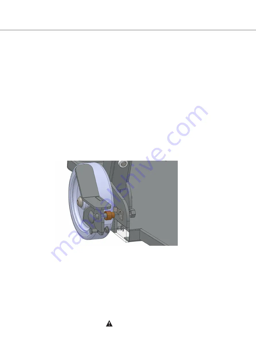
5. Position the brake pad spring behind the brake pad and align the hole with the corresponding hole in
the base - see illustration below.
6. Insert the brake pedal securing bolt through the square hole in the brake pedal, ensuring correct
orientation.
7. Insert the nylon spacing bush onto the brake pedal securing bolt, ensuring correct orientation. i.e. the
larger diameter head should be immediately adjacent to the brake pedal.
8. Insert the brake pedal securing bolt through the hole in the brake pad spring and the hole in the base.
NOTE:
Ensure the square shank of the securing bolt locates correctly in the square hole in the brake
pedal.
9.
Fit the M8 brake pedal domed securing nut to the brake pedal securing bolt and tighten to 20Nm using
a 14mm A/F combination wrench.
Repeat the ‘Brake Pedal/Pad Removal/Replacement’ procedure for the left hand brake pedal.
WARNING
Ensure the brakes operate correctly before returning the Hoyer Switch to service.


