vision
Snack Plus/Easy Combo
//
Vending
MNP86V03GBV00
Date: 2010/06/14 Rev. 0
PAGE 58 OF 62
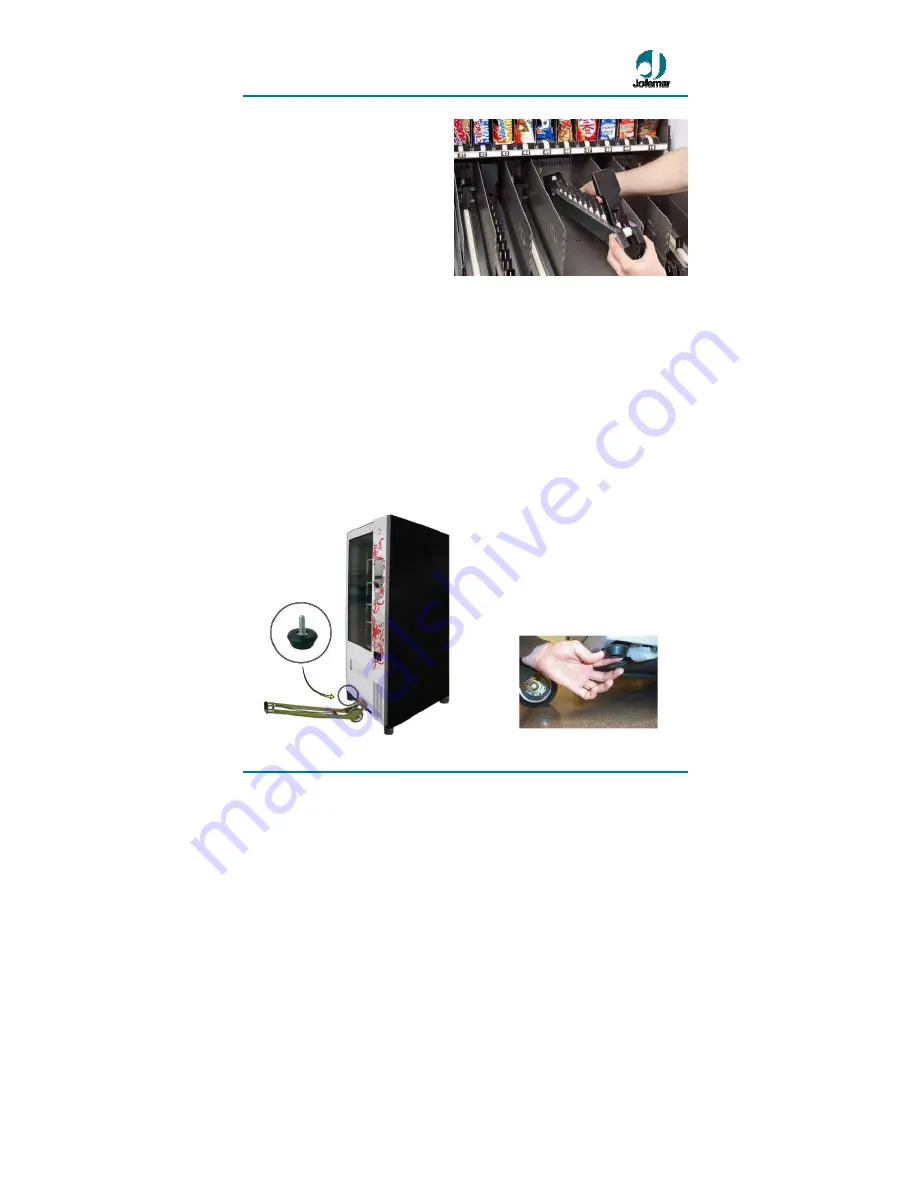
2. Fit the two metal tabs on the front of
the channel into the front guides of the
tray that you have selected or which
correspond.
3. Let the channel come down to the
base of the tray and assemble or fit in
the two metal tabs at the back of the
channel (motor area) on the guides of
the back part of the tray (check
whether the channel is aligned with the
centre of the tray).
4. Insert the tray connector in the
channel motor.
Fig. 46
To remove it, follow the same steps in reverse order.
7.4. Transport feet and adjustable levelling feet
Once the machine is on the ground (see fig. 49), it is advisable to remove the four
(plastic) transport feet for better stability, aided with the lifting jack as follows:
1. Raise the back, unscrew and remove the two plastic feet and let the machine rest on
the floor.
2. Raise the front, unscrew and remove the two plastic feet and replace with the two
adjustable levelling feet, making sure that they are fully screwed into the machine bottom
and slide the machine on its wheels to the desired position.
3. Once the machine has been placed
in its permanent position, raise the front
again with the lifting jack and level the
door of the adjustable levelling feet (left
and right see fig. 50), with this system
you can help to level the door perfectly,
thereby preventing scarping of he door.
Fig. 47
Fig. 48


