7.0 EXCAVATION
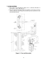
1. Dig a hole to accommodate the lifting unit to a minimum dimension of
24”Lx 84”W x 100”D. (See Figure 3).
2.
Dig a 9” deep trench (pipe chase for hydraulic and air lines) from the
cylinder pulley box center fitting to the location you have selected to mount
the pump and controls.
Figure 3 - Plan and Excavation
10
Summary of Contents for 40HP210ES
Page 9: ...Figure 1 Bay Layout Option A 8 ...
Page 10: ...Figure 2 Bay Layout Option B 9 ...
Page 12: ...Figure 4 Elevation 11 ...
Page 14: ...Figure 5 Cable Routing 13 ...
Page 15: ...Figure 6 Hydraulic and Air Connections 14 ...
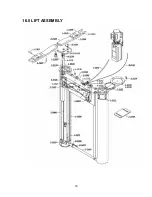
Page 25: ...16 0 LIFT ASSEMBLY 24 ...
Page 27: ...3 1026 1 Pump Stand Bolt Down Standard Not shown in figure 26 ...
Page 28: ...17 0 POWER PACK ASSEMBLY 27 ...


