background image

11.0 FINAL CHECK OF ASSEMBLED LIFT 

1. Check for air and hydraulic leaks. ___ 

2. Ensure all safety lock mechanisms are working correctly. ___ 

3. Check all fasteners, tighten if necessary. ___ 

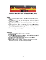
4. Operate lift to full stroke then lower to ground while checking for proper 

functionality. ___ 

5. Ensure Customer Care Kit is complete and given to operator. ___ 

a. Operation Manual ___ 

b. ANSI / ALI Lift It Right Manual ___ 

c. ANSI / ALI Safety Tip Card ___ 

d. ANSI / ALI ALIS Safety Requirements for Installation and Service 

of Automotive Lifts ___ 

e. ANSI / ALI Quick Reference Guide ___ 

6. Train end user on operation of the lift. ___ 


18

Summary of Contents for 40HP210ES

Page 1: ...TION MANUAL THOROUGHLY BEFORE INSTALLING OPERATING SERVICING OR MAINTAINING THE LIFT SAVE THIS MANUAL JUL 2008 REV A INSTALLATION and OPERATION MANUAL 10K 2 POST IN GROUND 40HP210ES 10K 2 POST IN GROUND 40HP210ES 6 3667 ...

Page 2: ...IONS 12 9 0 INSTALLATION INSTRUCTIONS 15 9 1 POWER PACK INSTALLATION 16 9 2 HYDRALLIC AND AIR CONNECTIONS 16 10 0 BLEEDING PROCEDURES 17 11 0 FINAL CHECK OF ASSEMBLED LIFT 18 12 0 OPERATING INSTRUCTIONS 19 13 0 AUTOMOTIVE LIFT SAFETY TIPS 21 14 0 TROUBLE SHOOTING GUIDE 22 15 0 REGULAR MAINTENANCE 23 16 0 LIFT ASSEMBLY 24 16 1 LIFT PARTS LIST 25 17 0 POWER PACK ASSEMBLY 27 17 1 POWER PACK PARTS LIS...

Page 3: ...vehicle manufacturer s recommended lifting points Raise the lift until the pads contact the vehicle Check pads for secure contact with the vehicle Check all arm restraints and ensure they are properly engaged Raise the lift to the desired working height 7 Some pickup trucks may require an optional truck adapter to clear running boards or other accessories 8 NOTE Always use all 4 arms to raise and ...

Page 4: ...ces installation operator training and owner employer responsibilities please refer to Lifting It Right ALI SM and Safety Tips ALI ST For additional instruction on general requirements for lift operation please refer to Automotive Lift Safety Requirements For Operation Inspection and Maintenance ANSI ALI ALOIM Installation shall be performed in accordance with ANSO ALI ALIS Safety Requirements for...

Page 5: ...2 0 SAFETY WARNING DECALS Be sure the operator is aware and understands all safety warning labels and follows them accordingly 4 ...

Page 6: ...ing legs attaching bolts stainless steel cables Cables measure 5 16 x 137 1 2 with adjusting allen bolts on ends 2 Lifting Superstructures 1 Cable Pulley Box with lid 1 1 2 I D x 21 Hydraulic Hose lift and pump 1 1 4 O D x 21 Nylon Airline run from air cylinder to push button on pump air valve 1 Wheel spotting plate 1 Plastic Bag containing located inside cable pulley box 12 7 16 x 1 1 4 Bolts and...

Page 7: ...cket for attaching the lifting superstructures to the pistons 1 7 16 Work gloves 3 pry bar for manipulating cylinders Level 6 Tape measure Set of screwdrivers Impact gun Torque gun Crain for lifting and installing cylinders Funnel Hammer drill or similar 1 4 and 1 2 concrete drill bits Caulking gun Some of the supplies required The necessary fittings for running shop air to air lift lock release b...

Page 8: ...ehicle to be raised 12 ft of ceiling height is sufficient for passenger cars 2 A minimum of 12 ft of stall space is required from both front and rear of lift center to nearest obstruction See Figure 1 2 3 6 ft is the recommended dimension plus desired work area between the lift center and side wall or nearest obstruction 7 ...

Page 9: ...Figure 1 Bay Layout Option A 8 ...

Page 10: ...Figure 2 Bay Layout Option B 9 ...

Page 11: ... to a minimum dimension of 24 Lx 84 W x 100 D See Figure 3 2 Dig a 9 deep trench pipe chase for hydraulic and air lines from the cylinder pulley box center fitting to the location you have selected to mount the pump and controls Figure 3 Plan and Excavation 10 ...

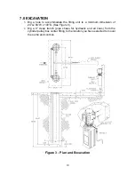
Page 12: ...Figure 4 Elevation 11 ...

Page 13: ...amount of locking leg that is extended If for instance the left side locking leg is extended further than the right loosen the right cable bolt and tighten the left cable bolt Continue this procedure until both locking legs are extended equally NOTE When adjusting cables hold the fitting on the end of the cable with vice grips to prevent turning 2 Attach the 1 2 O D hydraulic lines to the tee fitt...

Page 14: ...Figure 5 Cable Routing 13 ...

Page 15: ...Figure 6 Hydraulic and Air Connections 14 ...

Page 16: ...s of both cylinders to a minimum of 10 deep and 6 up the cylinders See Figure 3 Allow 24 hours for concrete to cure 5 Backfill with a clean dry washed sand fill to a level of 24 below floor grade Firmly tamp and check for plumbness frequently while backfilling 6 In the 9 deep trench from the pulley box to the wall where the pump lines will be installed use only 1 1 2 PVC electrical sweep as it mak...

Page 17: ...l pumping unit with AW 32 hydraulic oil I S O 32 with anti rust and anti foam agents approx 14 quarts DO NOT USE TRANSMISSION FLUID 9 2 HYDRALLIC AND AIR CONNECTIONS 1 Install the 1 2 O D x 21 hydraulic line and the 1 4 O D x 21 airline from the pump to the pulley box through the 1 1 2 PVC sweep 2 Connect the hydraulic line to the tee and the air line to the air cylinder elbow fitting both located...

Page 18: ...mp Step on the ends of these cylinders to force them back down 6 Add oil till recommended level in the tank is met 7 Attach the arm structures Torque 7 8 bolster bolts to 250 lbf ft 8 Raise lift fully and wipe pistons down with a light coat of silicone lubricant or WD 40 9 Lower the lift and record oil level in the pumping unit 10 Pressure check bleed plugs by inspecting them through the hole in t...

Page 19: ...ull stroke then lower to ground while checking for proper functionality ___ 5 Ensure Customer Care Kit is complete and given to operator ___ a Operation Manual ___ b ANSI ALI Lift It Right Manual ___ c ANSI ALI Safety Tip Card ___ d ANSI ALI ALIS Safety Requirements for Installation and Service of Automotive Lifts ___ e ANSI ALI Quick Reference Guide ___ 6 Train end user on operation of the lift _...

Page 20: ...T FACE OPPOSITE DIRECTIONS FLIP PADS CANNOT POINT IN THE SAME DIRECTION 1 Rotate arms to provide tire clearance 2 Center vehicle left and right over lift with wheel in proper spotting plate according to vehicle size 3 Position adapter pads at vehicle manufacturer s approved lifting points 4 If adapters are raised face front and rear in opposite directions Make sure the height adapters are position...

Page 21: ...ht and lower onto lift locks Avoid sporadic starting and stopping of pump motor if possible 5 To prevent pump motor damage always lower load onto safety locks when restarting motor in mid stroke Lowering 1 Make sure area under vehicle is clear of obstacles 2 Raise lift slightly 3 To disengage air operated lift safety locks push air lock release button in while pushing on handle to lower the lift 4...

Page 22: ... or to be in lift area during operation Never raise vehicles with anyone inside 5 Be sure work area around lift is clear free of obstructions debris grease and oil 6 Never lift a vehicle unless arm restraints are locked 7 Never attempt to operate a lift if it appears to be malfunctioning or if broken damaged parts are evident 8 Load lift carefully Check to be sure adapter or axle supports are in s...

Page 23: ...lve Clean the ball and seat and replace if necessary C Oil level low Check reservoir With lift in the down position the pump reservoir should be full 3 Motor runs but the lift picks up partial load only A Lift is overloaded Check lifts capacity and weight of vehicle B Relief valve setting is too low Remove hex head plug in the center of the pump and adjust pressure setting valve 4 Oil blows out br...

Page 24: ... 2 Inspect cables for fraying If fraying is evident DO NOT USE THE LIFT Replace cables 3 Grease swivel arm rub bars 4 Inspect arms for overload drooping from stretched or loosened arm bolts Have loose bolts tightened and stretched bolts replaced 5 Inspect the height adapters for damage and replace if necessary 6 Use a spray can of silicon lubricant on piston surfaces NOTE Clean and wipe down pisto...

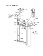
Page 25: ...16 0 LIFT ASSEMBLY 24 ...

Page 26: ...ic Cylinder HP210ES 1 3330 8 Piston Block Holder 2 2541 1 Bottom Spacer Pipe Weldment 6 3493 12 Hex Bolt 7 16 14 x 1 1 4 L 6 3494 12 Hex Nut 7 16 1 3473 2 Hyd Hose Cylinder 2P Inground 3 1000 2 Piston Weldment 3 0997 1 Pulley Box Weldment 6 3523 1 Air Lock Cylinder 6 0709 1 Swl Elbow 14 Poly x 1 8 NPT 6 0126 4 Hex Bolt UNC x 1 2 G5 6 3806 1 Bulkhead T 3 8 JIC Fitting 2 2544 1 Top Cover 2 2540 1 To...

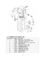
Page 27: ...3 1026 1 Pump Stand Bolt Down Standard Not shown in figure 26 ...

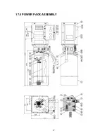
Page 28: ...17 0 POWER PACK ASSEMBLY 27 ...

Page 29: ... PACK 3 6 2158 SEAL SHAFT 0 5x1x0 25 4 6 1392 CAPSCREW 5 16 18 x 1 00 SOCKET HD 5 6 0916 MICRO SWITCH 6 6 2301 PACKAGE PLUG 9 16 SAE 7 6 2157 PLUMBING PLUG 9 16 SAE 8 6 2162 PLUMBING MAGNET 9 6 2164 SCREW TAPTITE TORX 10 6 2165 COVER ASY SUCTION 11 6 2166 CLAMPHOSEADJ INLET 12 6 3782 END HEAD UNIV 13 6 3553 BLANK COVER 28 ...

Page 30: ...875 RESERVOIR O RING 29 6 0782 PUMP ASSEMBLY 30 6 3795 RELIEF VALVE ASSEMBLY 180 BAR 31 6 2153 COMPRESSION TUBE NUT 32 6 0880 VALVE CARTRIDGE RELEASE MANUAL 33 6 1846 CABLE TIE 8 LONG WHITE 34 6 2156 WIRING ASSEMBLY AC 1PH FENNER 35 6 2301 PACKAGE PLUG 9 16 SAE 36 6 2302 ELECTRICAL STAKON NUT 37 6 2151 SPRING 0 48x0 063x0 42 38 6 2161 PLUMB PLUG 3 8NPT 39 1 3365 AIR LOCK BUTTON BRACKET 40 1 3471 H...

Page 31: ...18 0 AVAILABLE ACCESSORIES Figure 10 Truck Height Extension Adapter Part No 3 1028 Set of 4 30 ...

Reviews: