9.0 INSTALLATION INSTRUCTIONS
Before Installing:
After unpacking the lift, check shipping list to ensure that you have all
required parts.
Check unit carefully for shipping damage.
Handle unit with care. Dropping could cause internal damage.
Store unit indoors or under cover to prevent rusting or pitting from
condensation.
DO NOT ATTEMPT TO RAISE THE LIFT WITHOUT SUPERSTRUCTURES
ATTACHED.
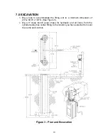
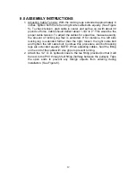
1. Attach a lifting chain to the upper spreader bar and lower cylinder
assembly into excavation, making sure the PVC through hull fitting is
facing the front of the bay where pumping unit will be installed.
2. Secure cylinders to a finished height of 1/8” above finished floor grade.
Wooden 6” x 6” planks and 1/2” threaded rod help achieve proper
positioning. NOTE: Slope concrete away from lift in all directions.
3. Place a spirit level across the top of the pistons (not the cylinder
flanges) in two directions and adjust until pistons are plumb. Use a 6 ft.
level from one piston to the other to make sure they are level with each
other. Correct by adjusting as necessary.
4. Pour concrete around bases of both cylinders to a minimum of 10”
deep and 6” up the cylinders. (See Figure 3). Allow 24 hours for
concrete to cure.
5. Backfill with a clean dry washed sand fill to a level of 24” below floor
grade. Firmly tamp and check for plumbness frequently while
backfilling.
6. In the 9” deep trench from the pulley box to the wall where the pump
lines will be installed, use only 1-1/2” PVC electrical sweep as it makes
its turn up the wall to the pumping unit (leave the PVC sweep at least
6” above the floor grade to prevent water from entering the box).
7. Connect the PCV sweep fitting to pulley box assembly. NOTE: Make
sure to place an “O” ring gasket between the PVC fitting and the outer
surface of the pulley box assembly. Fully tighten the nut to prevent
leakage upon pouring of the concrete. (See Figure 5).
8. Complete backfill to a level of 9” below floor grade.
9. After rechecking plumbness in all directions, pour and finish concrete
making certain that cylinder flanges are 1/8” above finished grade.
Note: It is recommended to slightly taper concrete up the cylinder to
prevent any standing water around cylinder flange.
10. Install wheel-spotting dish in proper location. (See Figure 1 & 2).
11. After allowing 48 hours for concrete to cure, attach lifting structures to
pistons and equalizer struts.
15
Summary of Contents for 40HP210ES
Page 9: ...Figure 1 Bay Layout Option A 8 ...
Page 10: ...Figure 2 Bay Layout Option B 9 ...
Page 12: ...Figure 4 Elevation 11 ...
Page 14: ...Figure 5 Cable Routing 13 ...
Page 15: ...Figure 6 Hydraulic and Air Connections 14 ...
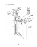
Page 25: ...16 0 LIFT ASSEMBLY 24 ...
Page 27: ...3 1026 1 Pump Stand Bolt Down Standard Not shown in figure 26 ...
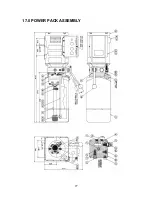
Page 28: ...17 0 POWER PACK ASSEMBLY 27 ...


